Custom 1×8 combo tube amp: build log #3, finished!
I’ve started putting together the electrical parts of the amp. This is where the real fun begins! This log is going to be rather picture-heavy if I can help it, with explanations placed where pictures are worth too few words.
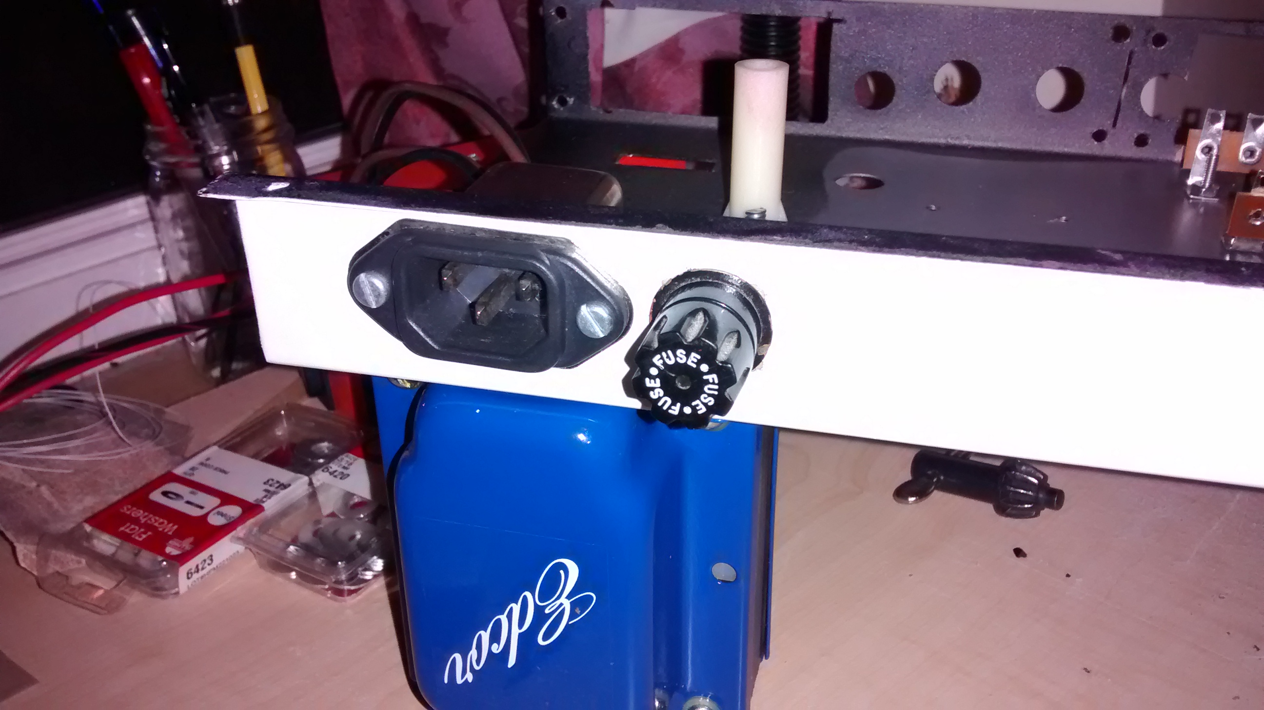
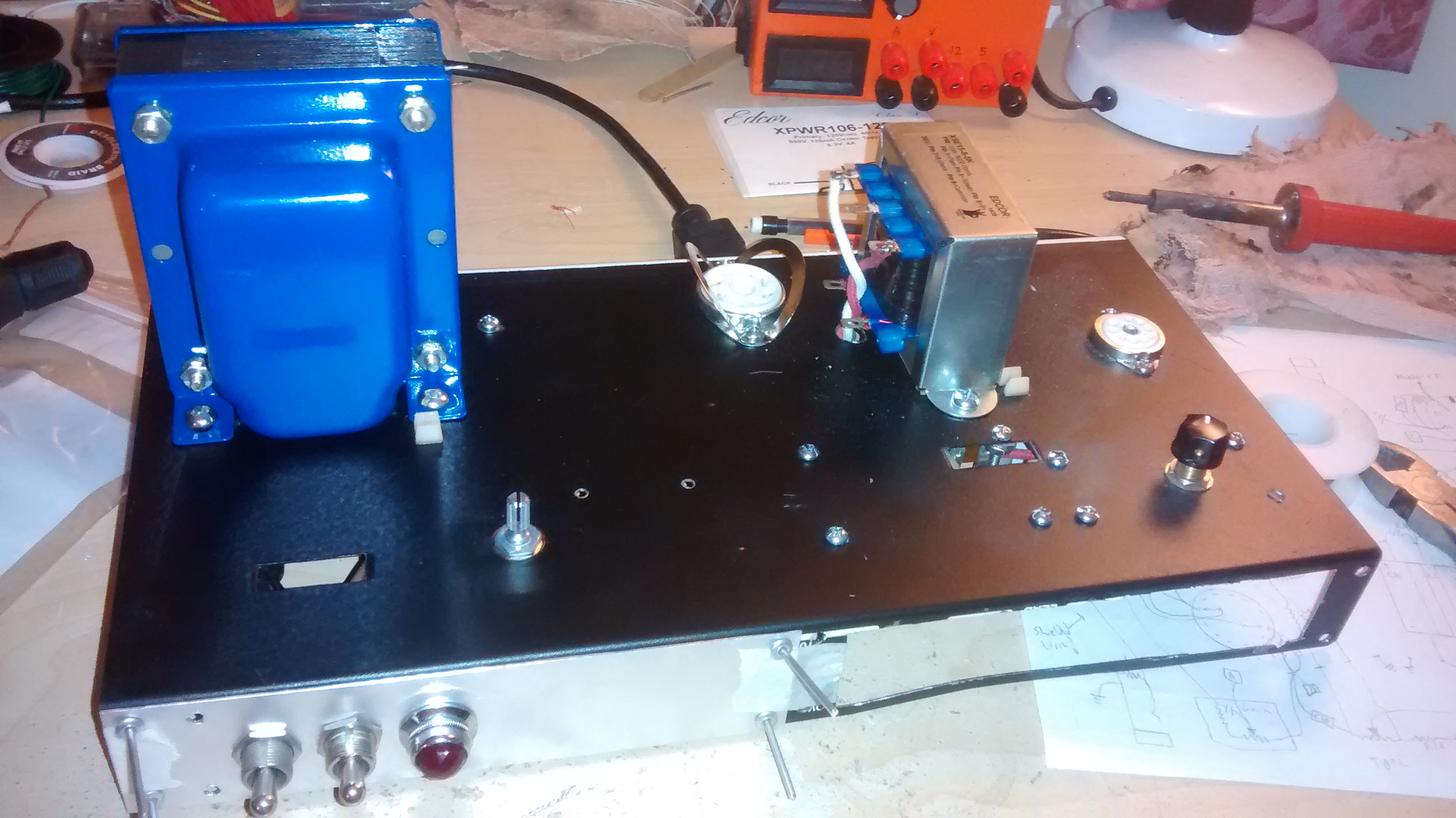
First comes the power input section. The power transformer gets mounted in its holes, as well as the IEC jack and fuse holder.
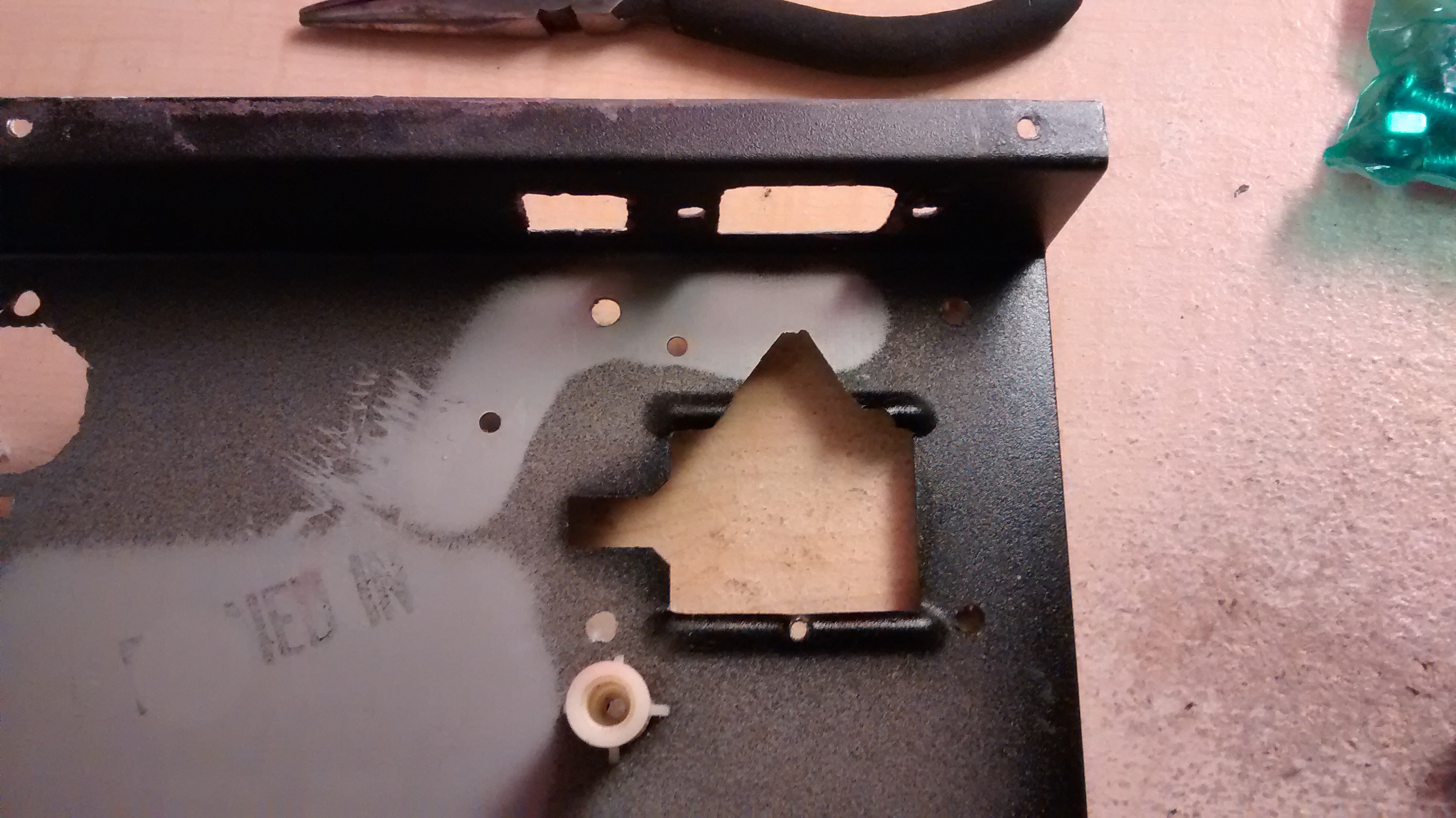
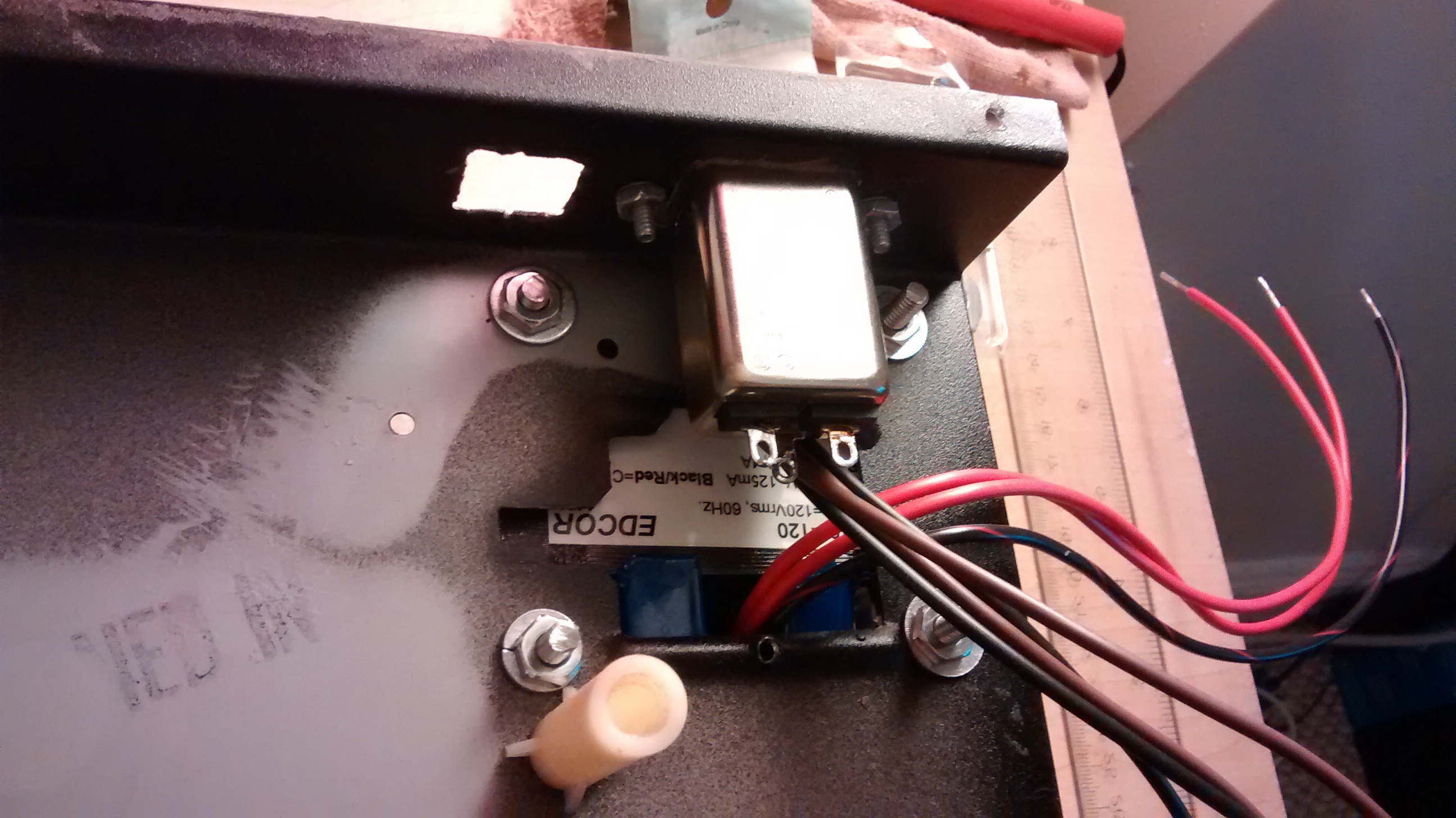
My square fuse holder from the Carvin amp ended up cracking and became far too loose in the hole I made for it, so I improvised and made a large circular holder fit instead.
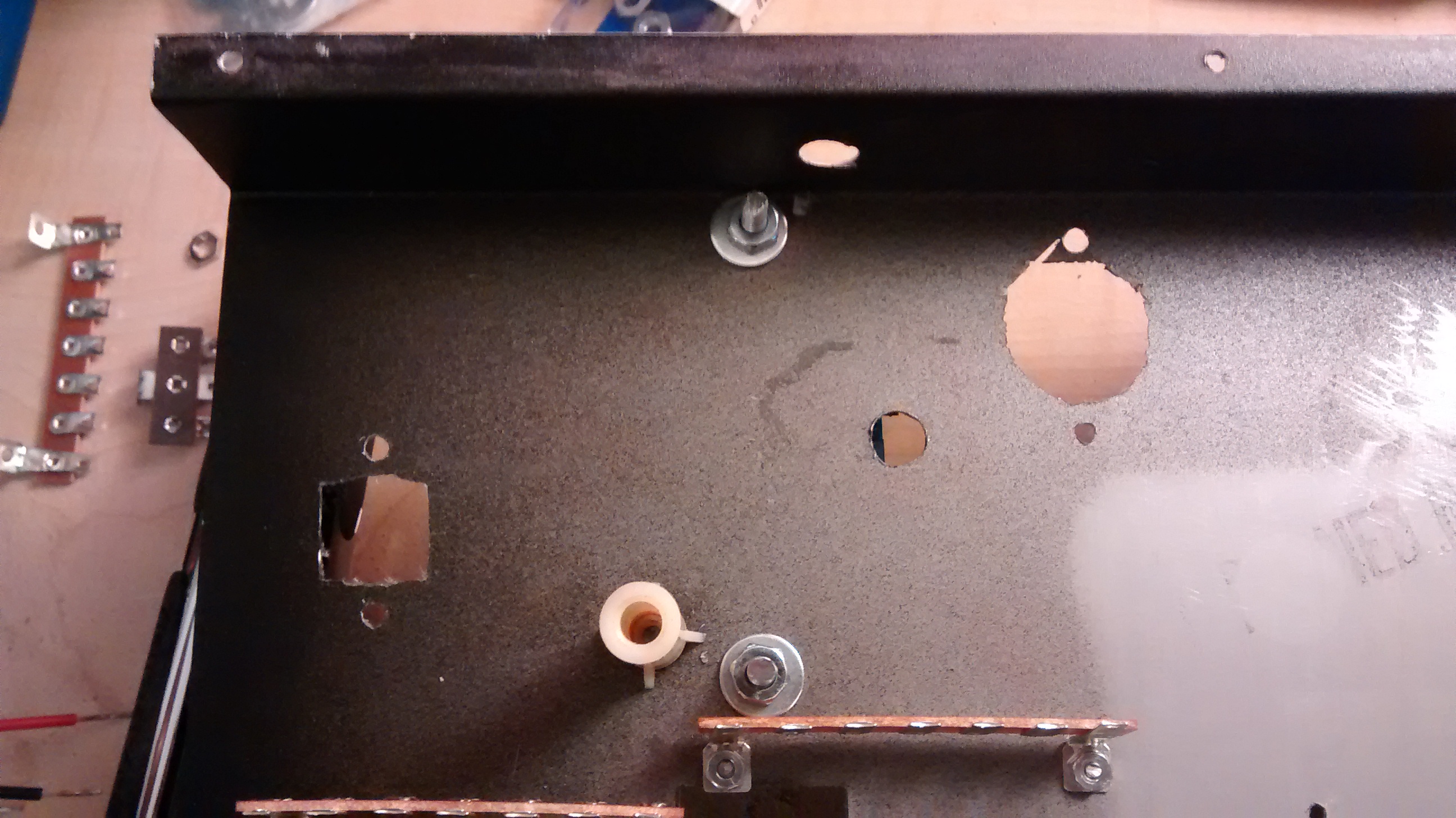
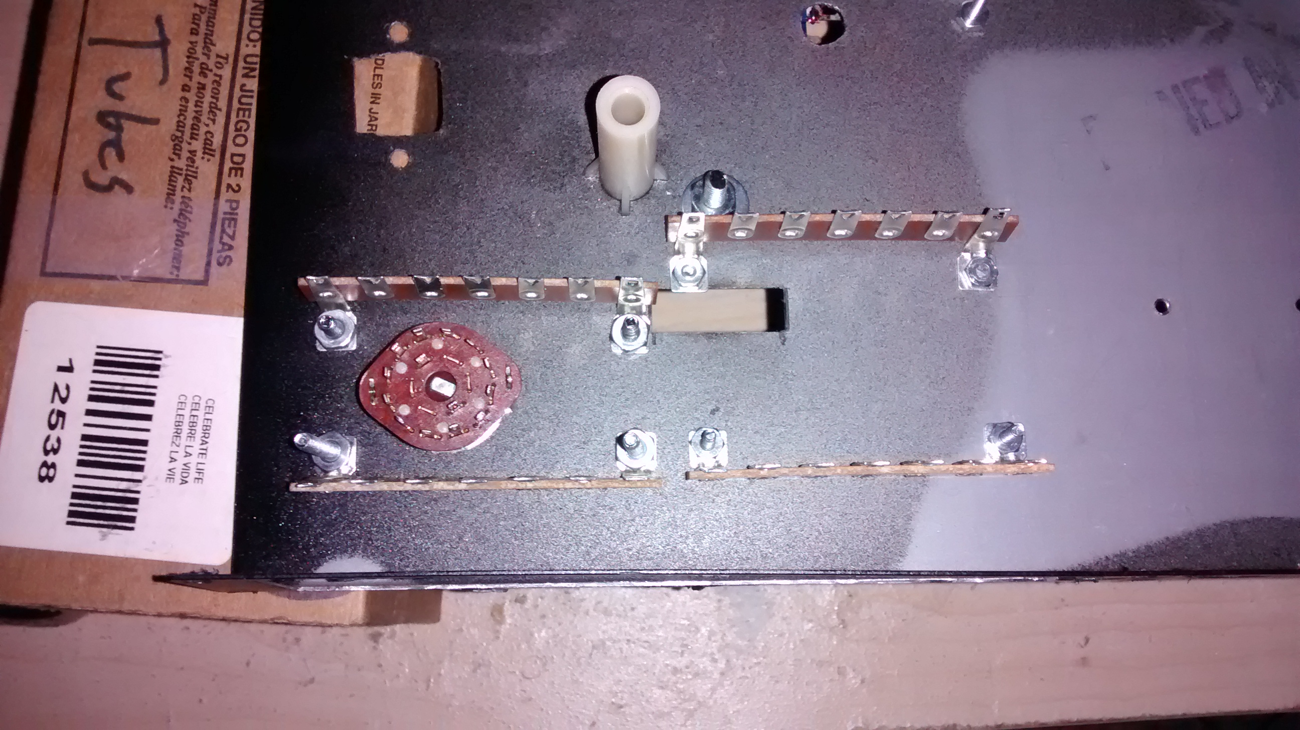
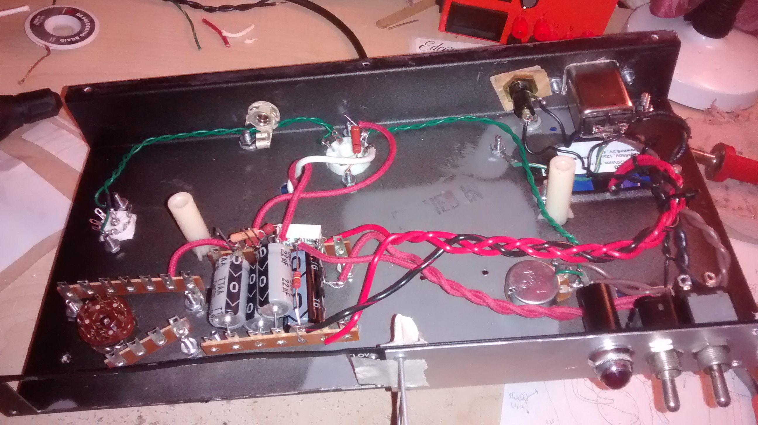
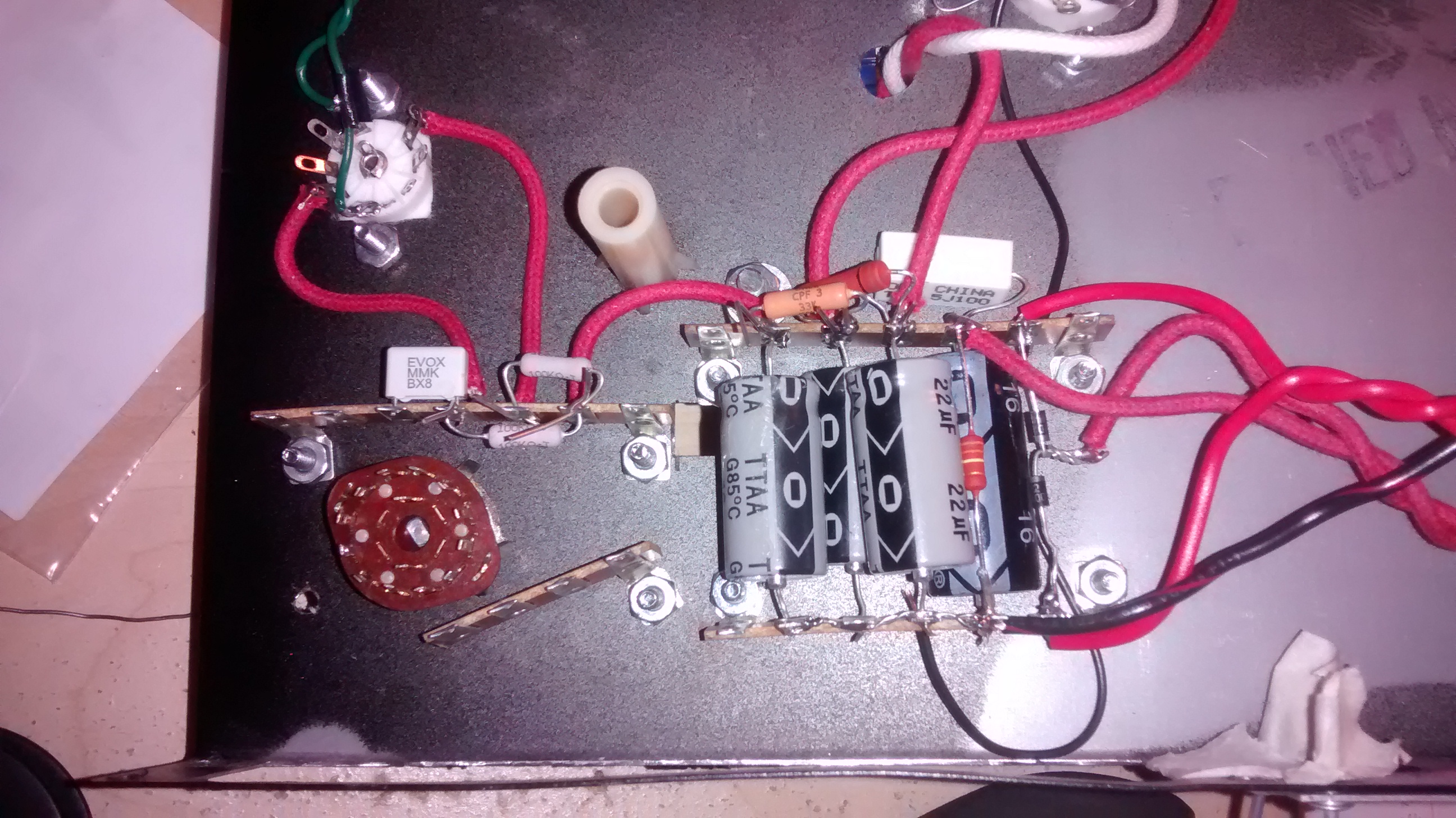
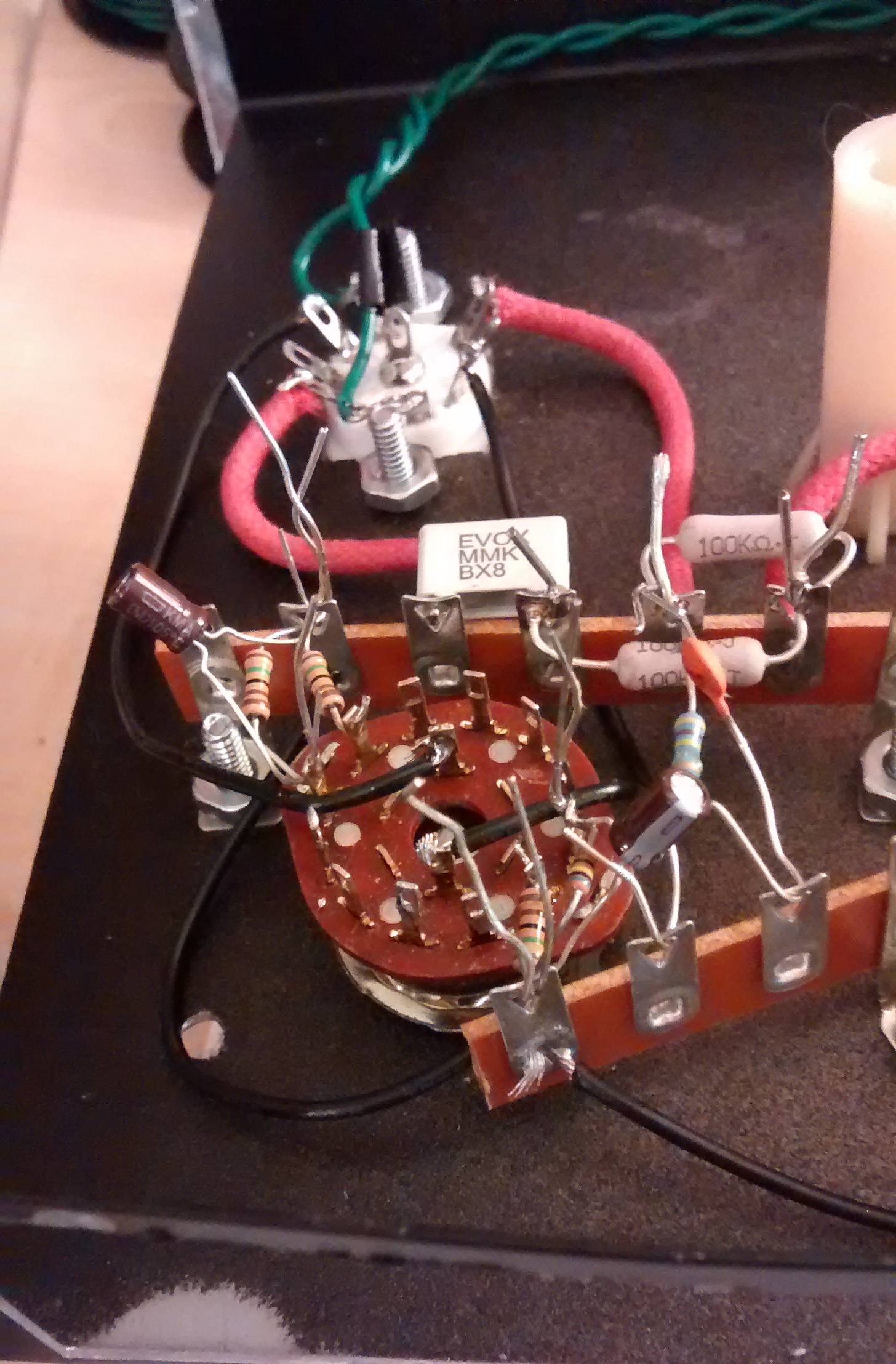
I mounted the terminal strips with some temporary screws to start fitting components. You’ll notice the circular doo-dad in between one set of terminal strips. That is a two-pole six-throw rotary switch that I decided to add in, to allow me to experiment with different biasing of the preamp tubes without switching out components. At first I considered just building the amp in a very simplistic fashion with only the default biasing and no switch, but this toy was just too attractive.
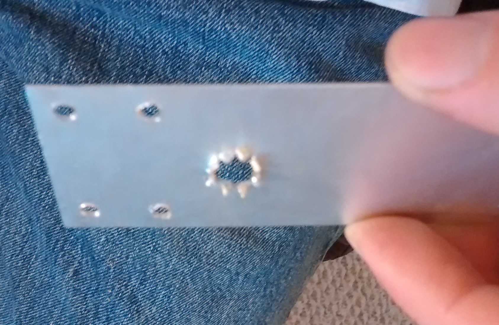
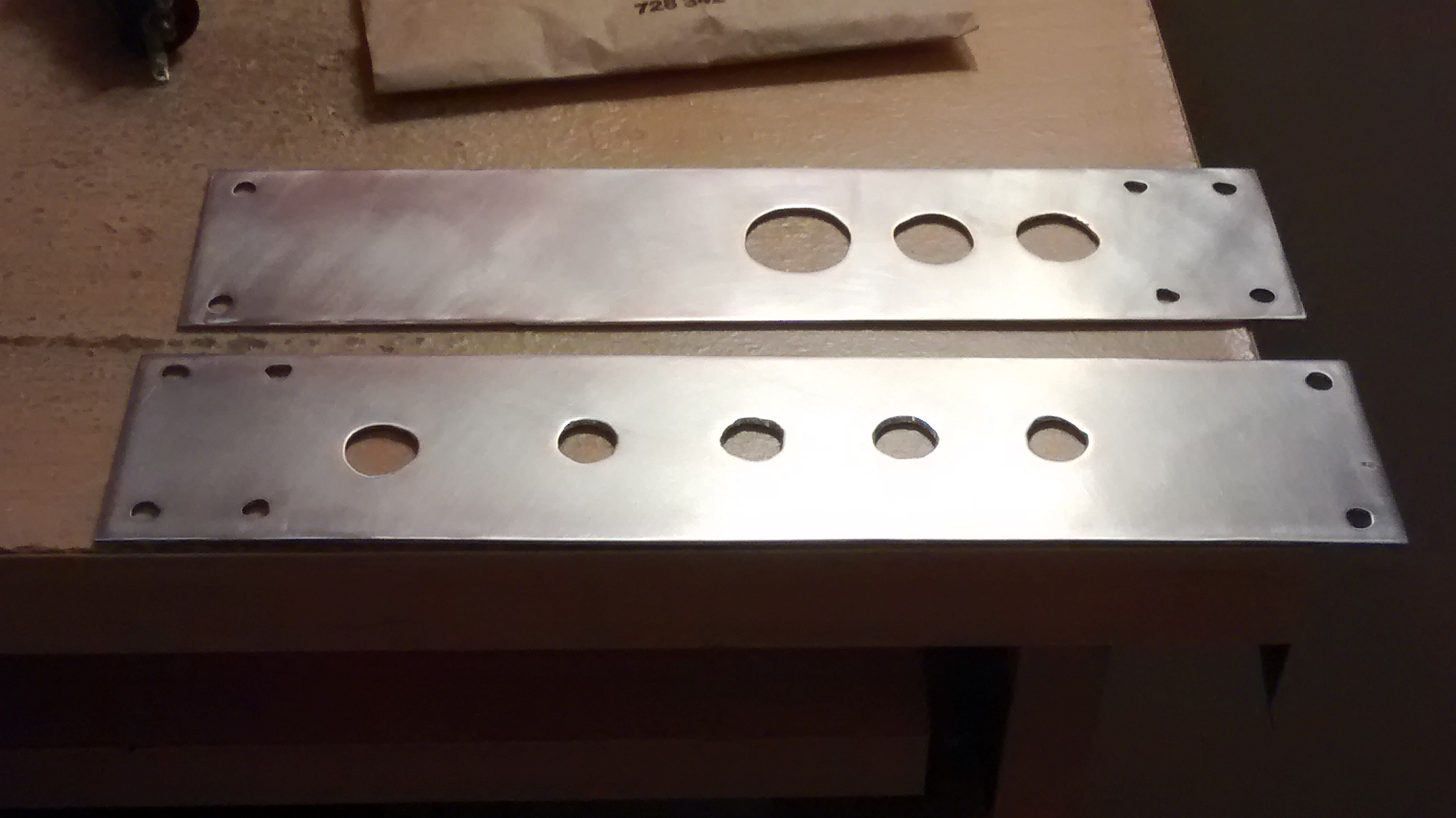
Next I started drilling holes in the right-side face plate for power switches and the pilot light. This was slightly tricky because my switches required larger diameter holes for mounting than I could make with my drill bits. I experimented with a hole cutting technique whereby I used a Dremel cutting wheel to cut across a to-be holes center like one might with a pizza, then tried peeling back the pieces to be cut off at the base yielding an octagonal hole. This worked, but not very well. I ended up just drilling the largest hole I could, then enlarging the hole with a circular file. This took about the same amount of time with much less chance of aesthetic error.
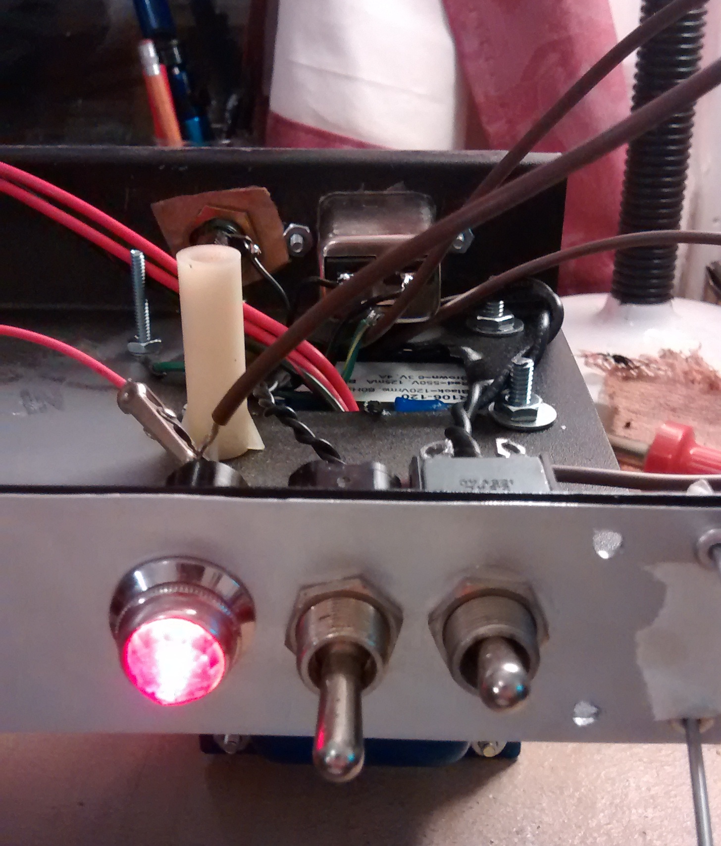
Once the switches and pilot light could be mounted, I wired them in to the circuit and tested that the jack, fuse, switch, pilot light, and of course power transformer functioned as expected.
I continued by adding in the filament wires and power supply section. An addition I made to the filament circuit was that of a “humdinger”. This is a low-value potentiometer (500 ohm in my circuit) with the outer poles tied to each side of the filament supply and the center tied either to ground or some point of DC elevation. The purpose is to allow the user to “balance” the filament circuit for best hum rejection.
Once the rectifier, first filter capacitor, and standby switch were in the circuit, I did another power-on test to make sure everything was functioning properly.
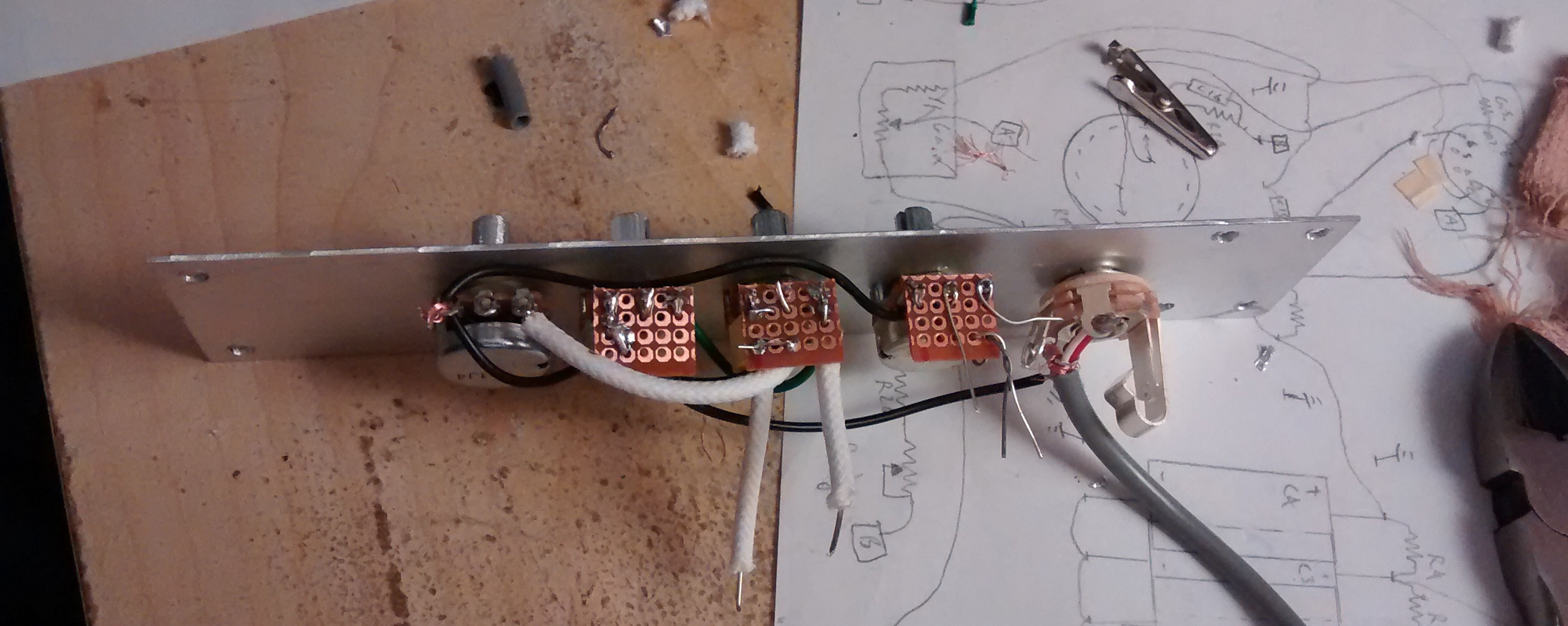
From here more components fell in to place. I’ll add descriptions to the photos below to tell what’s what. You might notice that there are some long leads and unsoldered portions in the pictures below. I usually don’t solder things in place until I’m sure I won’t have to move them or add something additional to a terminal, and even after soldering them I leave the leads on until I’m sure I won’t possibly need to remove the component and reconfigure it someway.
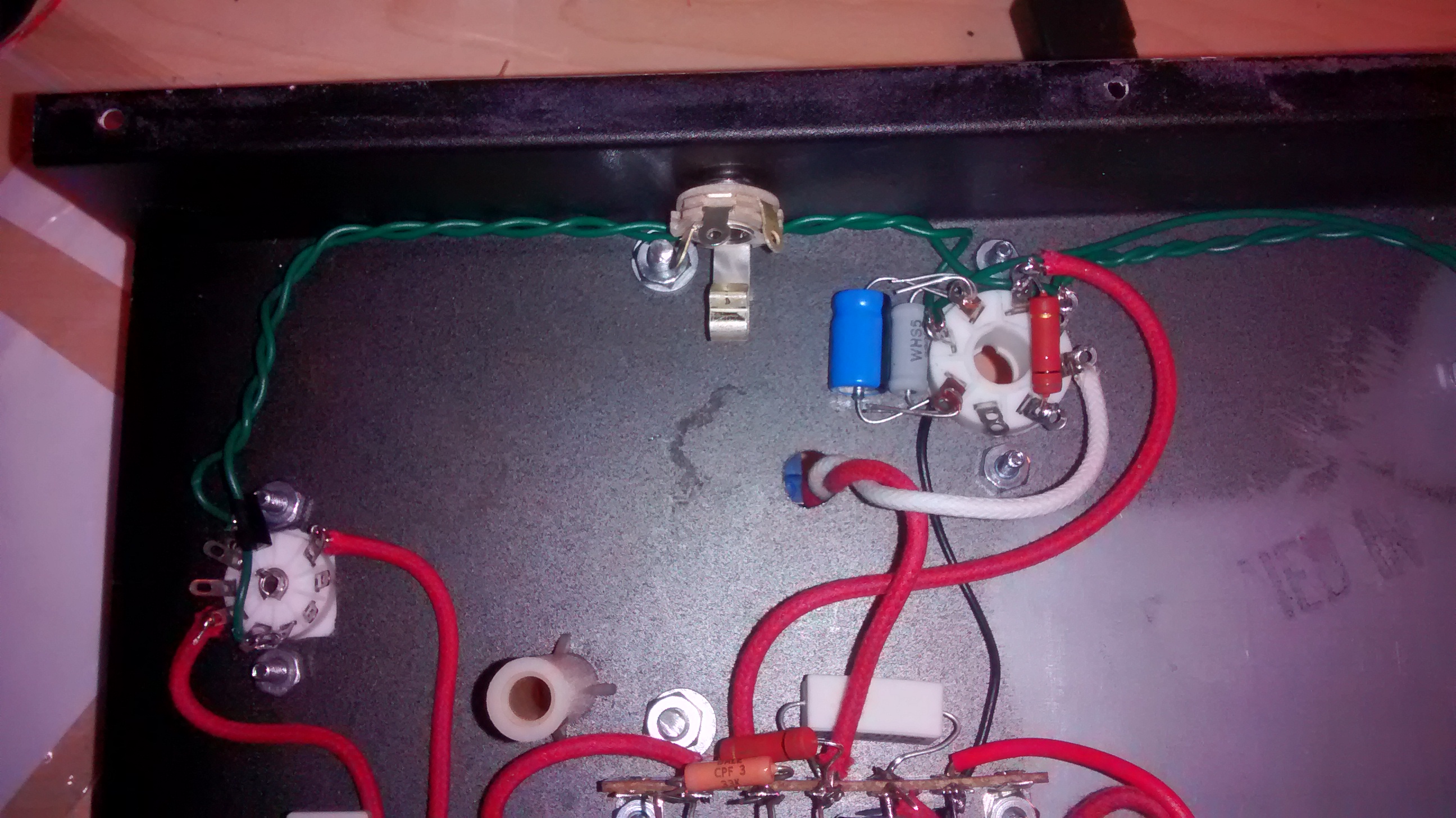
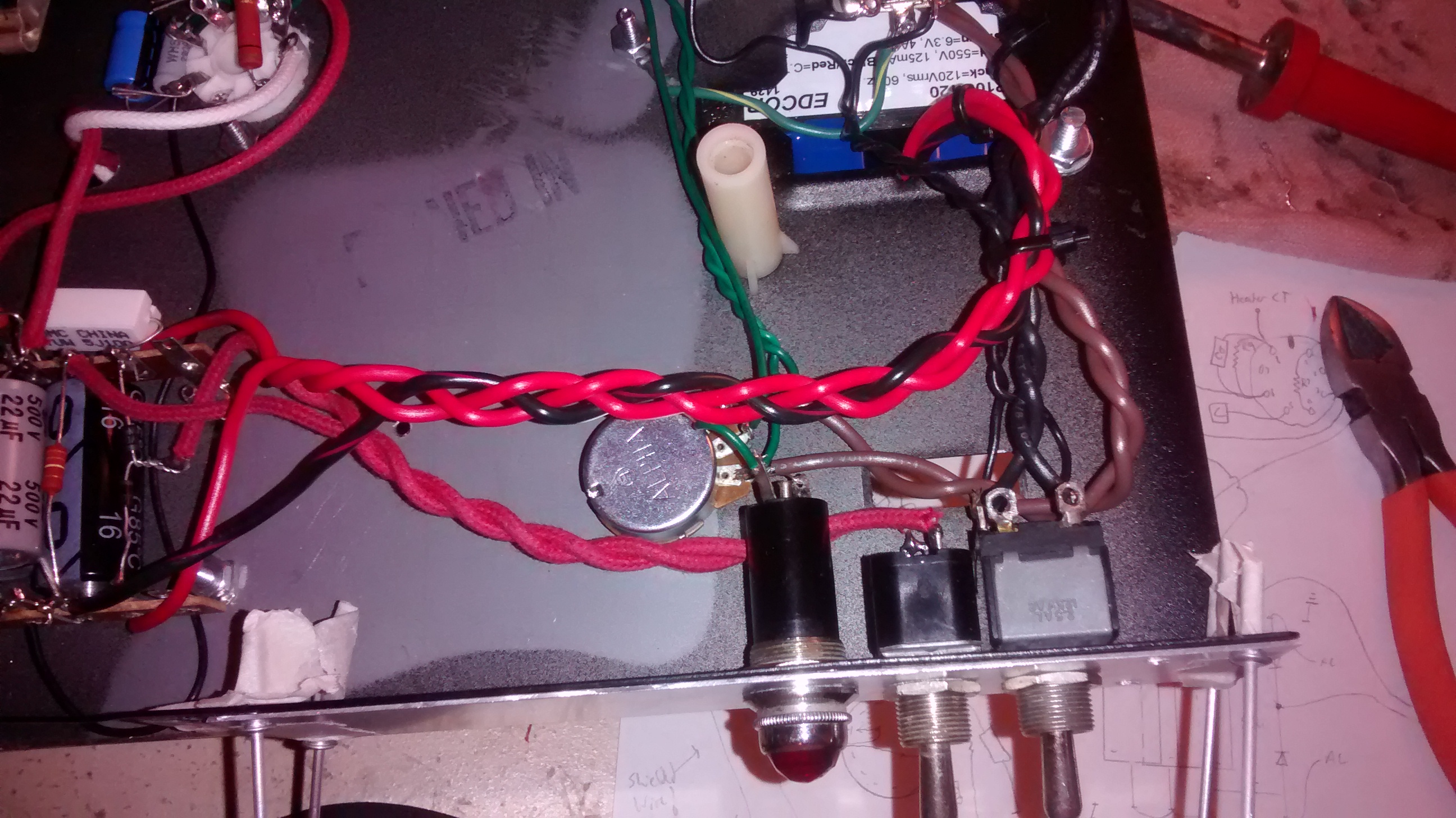
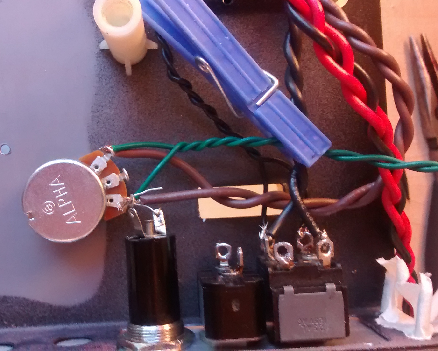
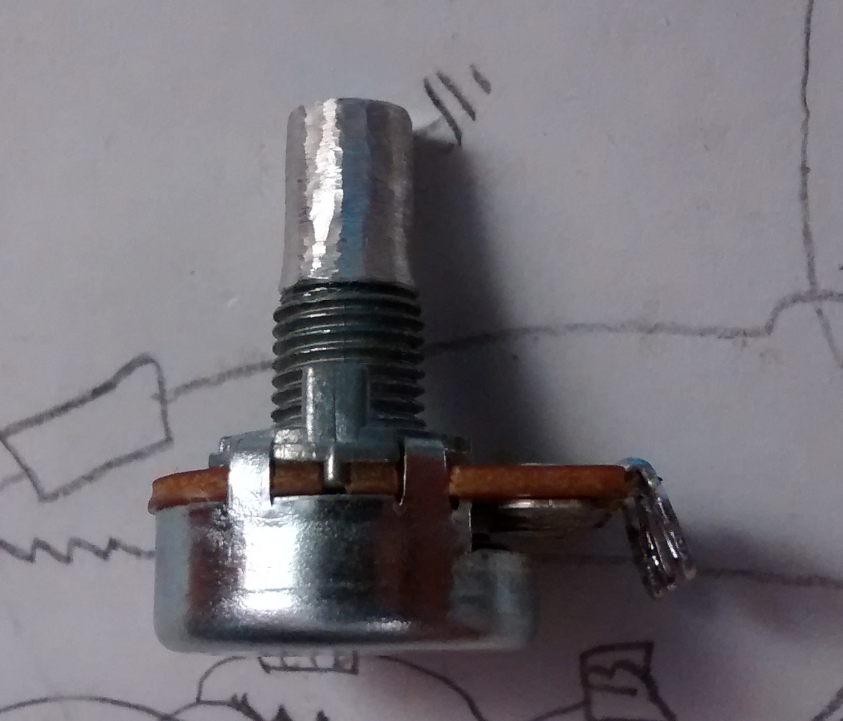
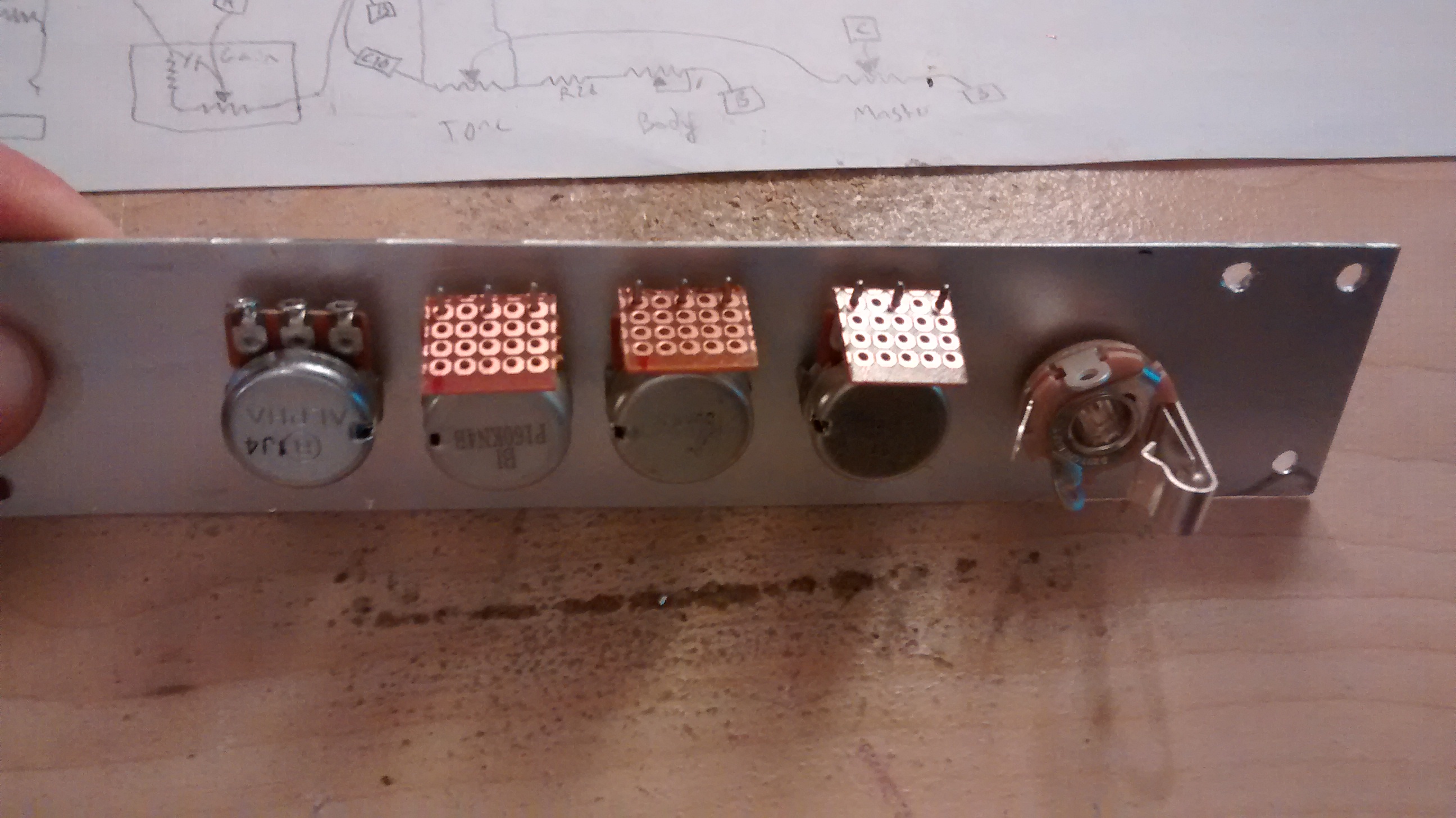
I’ve gotten to the point where I can start putting controls on the front panel. Save for the two pots I used in the tone circuit and the input jack, these were components I had just laying around. One of these was a 1M pot I used for the master volume who’s shaft was just slightly too big in diameter for the knobs I wanted to use. Easy enough to solve with a Dremel grinding wheel!
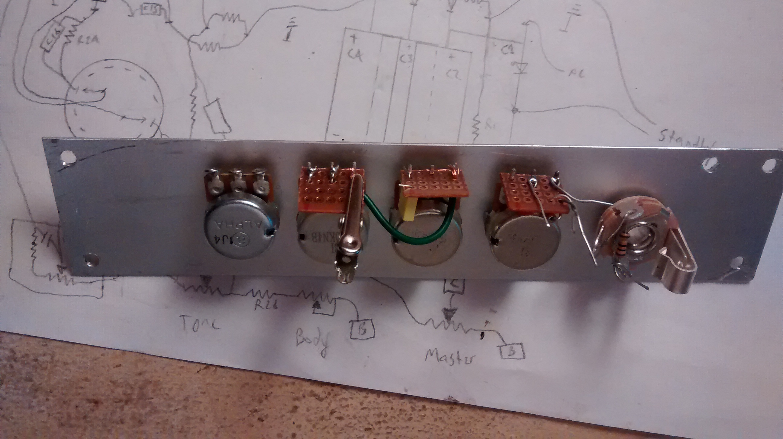
The rest of the potentiometers had PCB style solder-pins, which would have made point-to-point soldering rather difficult. I solved this by cutting out small segments of perfboard that could be soldered to their terminals, providing a mounting place for some of the tone-circuit components.
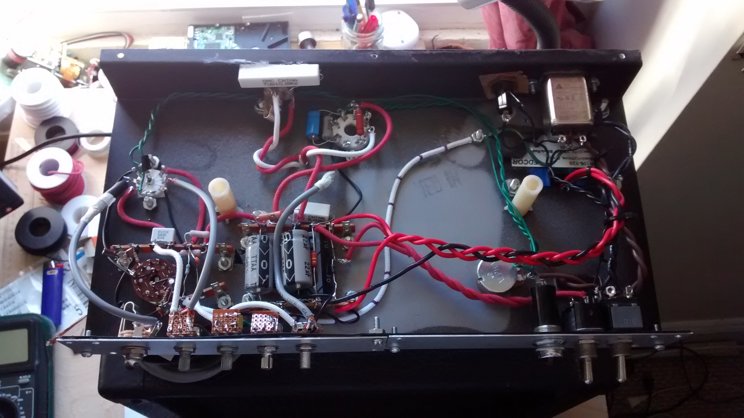
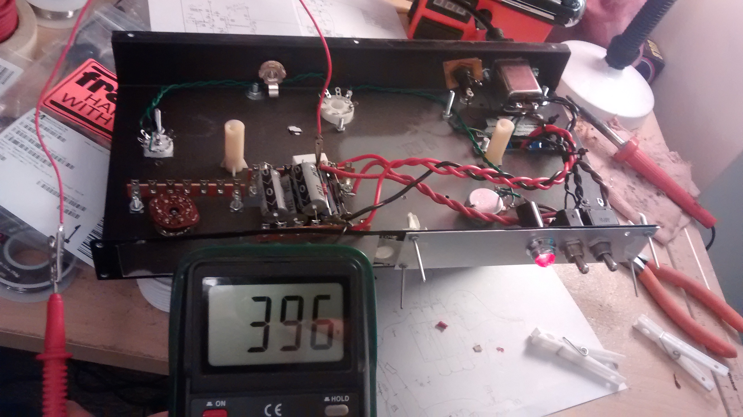
And with that, it looks like everything is wired up! Now I can power it up and do some testing. I recommend reading this page for some tips that will help you NOT blow up your amp the first time you turn it on. I more or less followed these steps as I was building the amp, with power-on tests at various stages. This last stage involves powering up the amp without tubes, and making sure that power is getting to where it should be and not anywhere else! All looks good, so now I can stick my tubes in and see what happens!
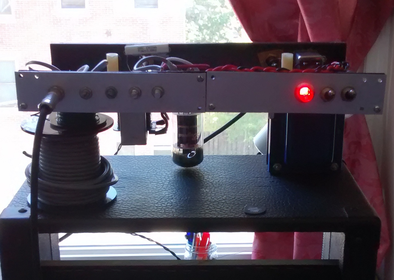
It lives! When first turning it on, it’s important to NOT immediately start strumming your guitar with everything cranked. Listen for any hum coming through the speaker first, the absence of which might indicate a problem. For example if the speaker isn’t hooked up to the output transformer, the output transformer is going to blow up as soon as any significant signal is applied to it. My amp hummed just enough to be audible, so I plugged in my guitar and slowly turned up the volume. To my delight, everything seemed to be working just fine.
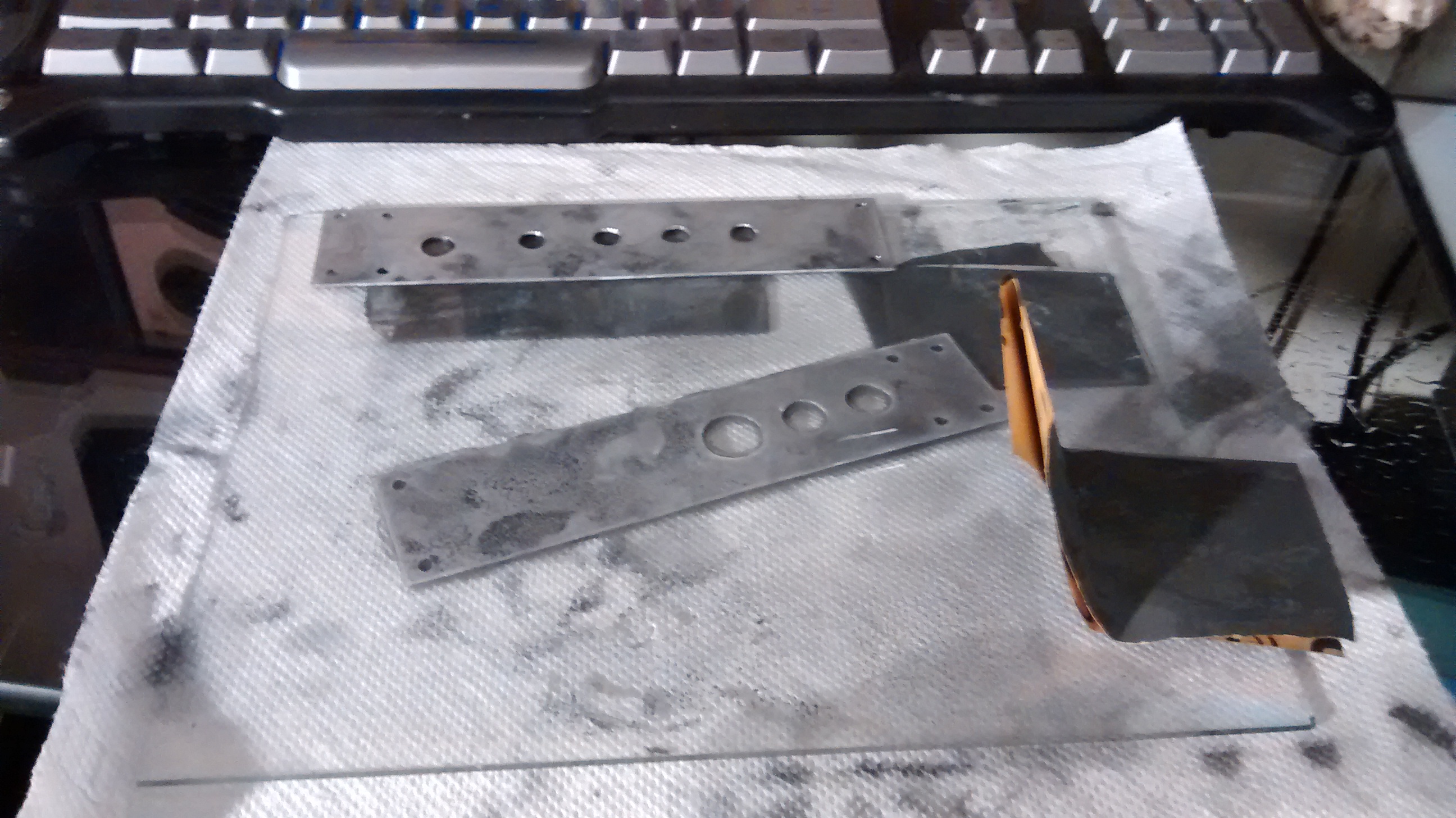
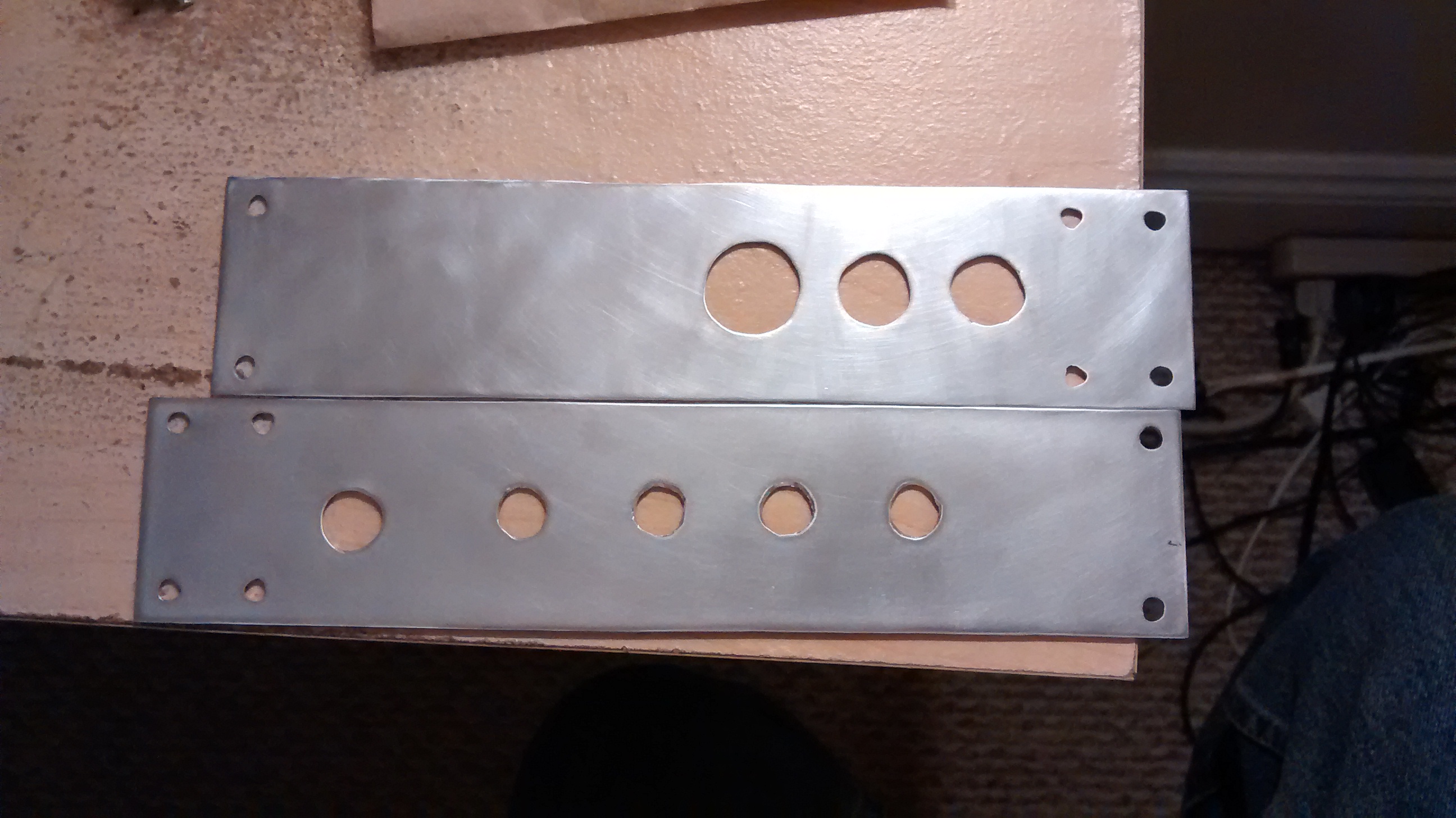
Terrific. Now I can polish up my faceplates and put the amp together permanently, right? Well, that’s what I decided to do next anyway. The faceplates are made of steel, and looked pretty nice to begin with but in the process of cutting and drilling they became rather scratched and in need of a face lift (pun intended). The process I used to polish up the surface is identical to the one I use when lapping CPU heatsinks. I had an assortment of wet/dry sandpaper (the gray kind) of varying coarseness, specifically 320, 600, and 1000. I set up on a flat surface which happened to be a pane of glass since it’s easy to clean. I dripped some water on the faceplates and began sanding them with the 320 grit sandpaper, going in large circles so that only extended curves would appear in the marks left on the faceplates. I repeated this process with the 600 and then the 1000 grit sandpaper to achieve a nice polish. Moving in large circles is important (in my opinion) because if you do small swirls or straight lines it leaves strange (read: ugly) reflective patterns on the metal even if no actual “scratches” are visible. The slight curves are much more appealing and give the surface a more continuous and consistent appearance. Ta-da! Now they’re all shined up and look pretty good:
Next I mounted the faceplates, attached and soldered in all the controls and finally riveted the faceplates to the mounting points on the amp chassis. I put the whole she-bang in the speaker cabinet and reveled in my creation.
That was great, for a very short while. After putting the amp through it’s paces I noticed some problems. The most obvious was that when I turned the “mid scoop” control to the maximum position in one direction, all the sound would cut out.
The other problem I noticed was that when I turned the master volume up all the way, the anode of the power tube would slowly start to glow red (red plating) after a short while. With some of the preamp biasing settings, sound would also cut out entirely at maximum master volume. Annoying, to say the least.
The first of the problems was rather easy to fix, I had forgotten a resistor on one of the poles of the mid-scoop potentiometer indended to keep all signal from shorting to ground. Inserting the resistor kept the signal from shorting to ground. This made the tone stack operate correctly.
The second problem was a little more insidious, but was a result of a poorly thought out design modification on my part. I had swapped the Fender style tone stack for a Big-Muff style stack (with mid knob) to eliminate one knob from the Fender-like setup (I like simple controls). The various examples of the Big-Muff tone stack one might find online are a bit agnostic to what your input/output connections are. Reasonable to expect a designer to consider this, but I pretty much just dumped the stack in to the circuit immediately after calculating the values to achieve the frequency response I wanted. The cause of my troubles was the DC voltage appearing on the grid of the power tube. So when the master volume was turned up a higher DC voltage was allowed to appear on the grid of the power tube thus causing it to draw more current which caused the over dissipation and red-plating. I fixed this by placing a 1 nanofarad coupling capacitor immediately after the tone stack and before the grid of the power tube. This eliminated the DC voltage on the grid and cleared up this nasty problem.
I made one more change after playing with the amp a bit longer. The low end sound was rather flabby and mushy in my opinion, which I did not like. Specifically this was blocking distortion, and if you know what that is you know it sounds terrible. This is caused by too much low frequency being passed between gain stages by the inter-stage coupling capacitor, in this case the first and second (only) gain stages. The initial value specified by the P1-eXtreme schematic was 22 nanofarad, which I swapped for a 2.2 nanofarad capacitor. This cleared up the blocking distortion greatly.
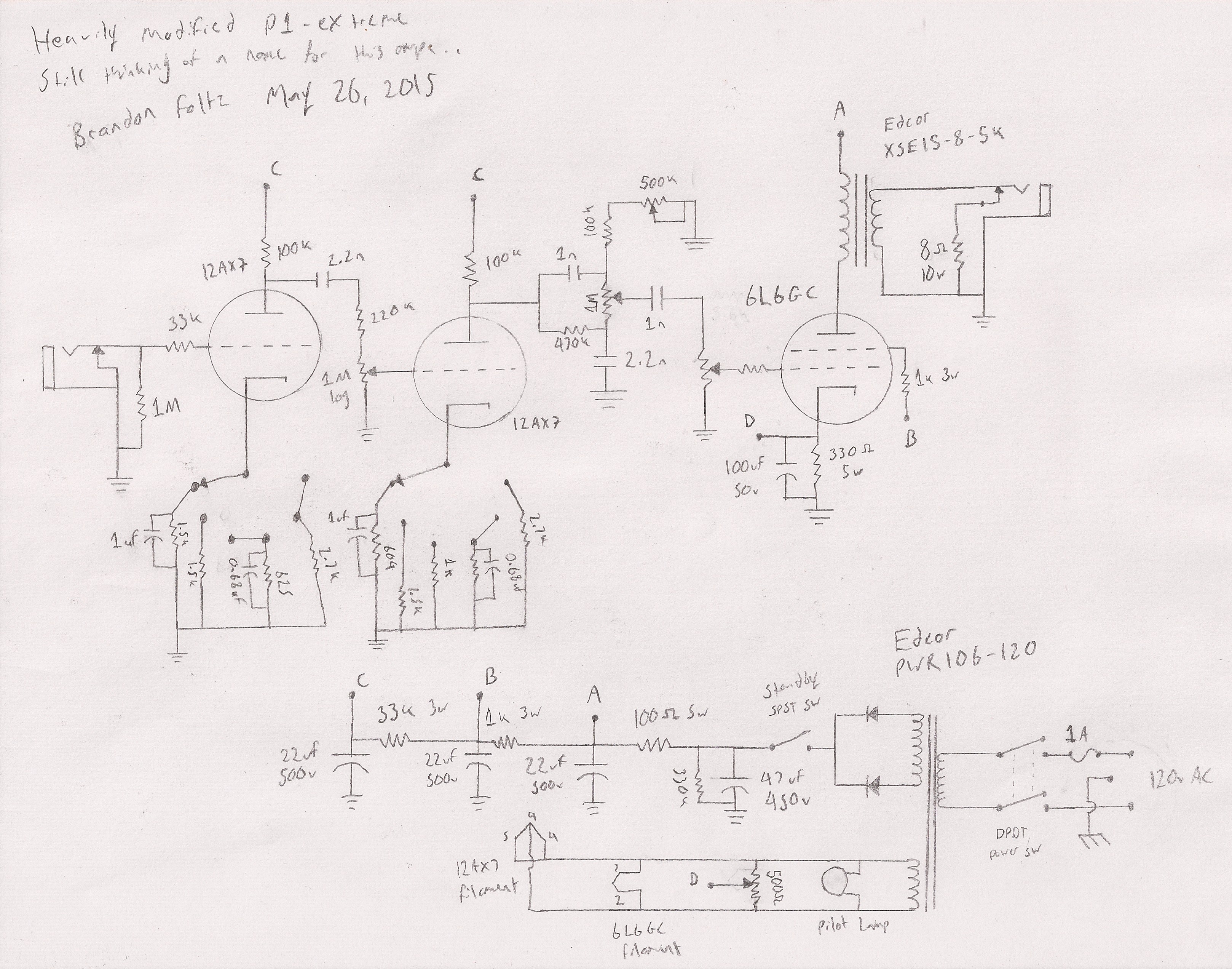
Hooray! I think that about wraps up the construction and tweaking of this amp. The final schematic I arrived on was this:
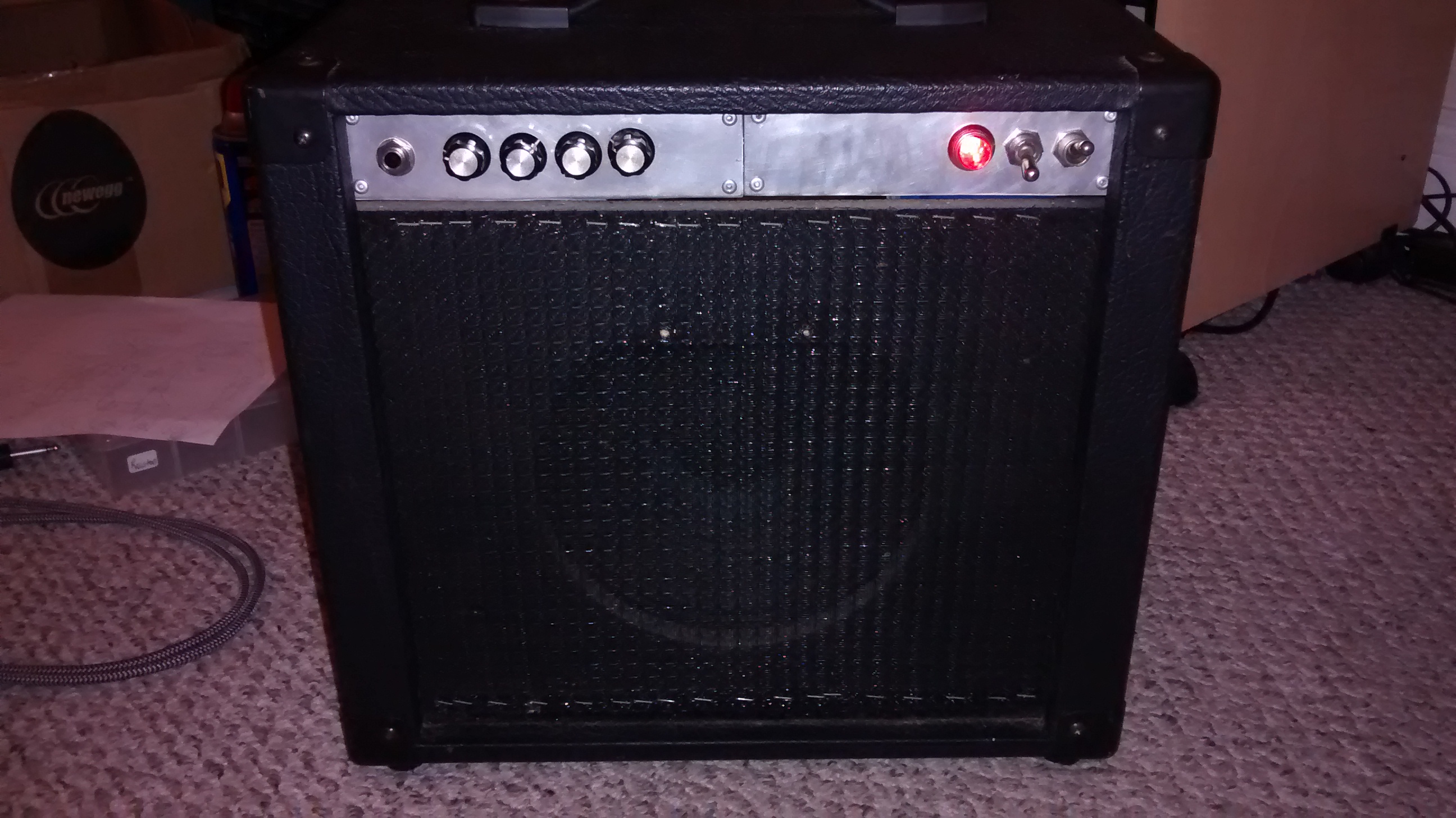
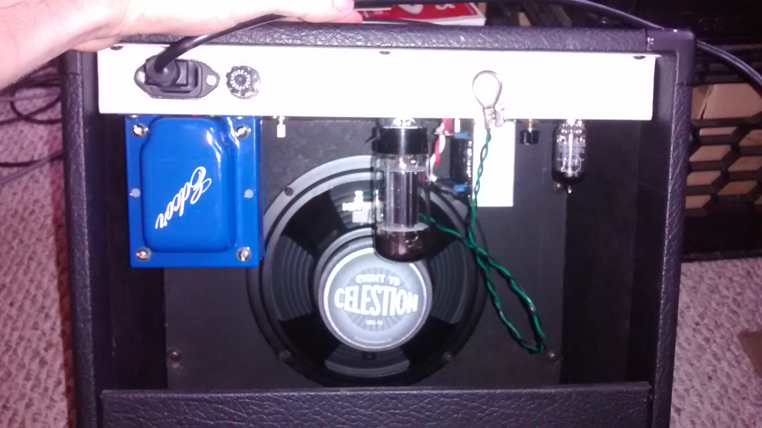
And some final glory shots of the amp completely assembled:
So now enjoy the fruits of my labor, and have a listen to the clip I recorded to sample some of the tones.

