Custom 1×8 combo tube amp: build log #1
Some weeks ago I decided to build a tube amp. I wanted something simple, with few parts, that sounds good. I decided to work from the AX84 P1-eXtreme amplifier design.
I considered buying a metal chassis for the head and then building a wooden head enclosure and wooden speaker cab by hand. I figured it would be easy to find some half-inch planks of wood to work with. I found that short of tearing apart some solid wood furniture and reusing the pieces, building things from wood stock is rather difficult. It commonly comes in one-inch slabs and would require several rather large and expensive machines to work with. I only have hand tools like a drill and Dremel at my disposal, so another route was necessary.
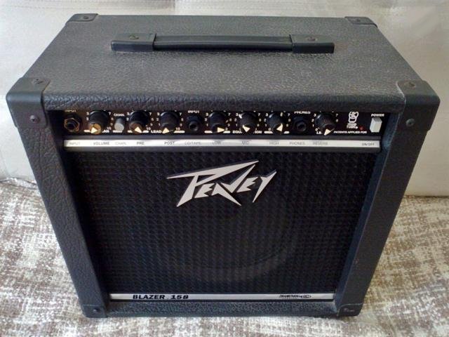
After a bit of thought, I decided to convert a cheap solid state combo into a tube amp combo. The advantages here are that the speaker cab is already constructed, and I could use the existing metal chassis to house the new components. I picked up a Peavey Blazer 158 on Craigslist for $44. After tearing out the solid-state guts I was left with an empty box ready for modding.
The first thing I did after gutting the amp was replace the cheap Chinese speaker with a Celestion Eight-15 I bought on eBay for $37 after shipping. It’s a fifteen watt, eight inch speaker that sounded pretty dapper judging by the YouTube demos I listened to.
Since I decided to build on an existing design, I could go ahead and order more parts. The P1 amplifiers specify Hammond transformers, but I decided not to use those. I went with Edcor instead, and ordered the XPWR106 power transformer and XSE15-8-5K single ended output transformer. These transformers are nearly identical to the ones specified in the P1-eXtreme design, save for the Edcor output transformer having only an 8 ohm tap instead of 16, 8, and 4 ohm taps. I’m building a combo, so the extra output taps aren’t strictly necessary. I also like that Edcor transformers are hand made in the USA! These bad boys cost me $83 after shipping.
I started working on some schematic mods to reduce the parts count at this point, but it seems fruitless to mention them right now because I may decide to change things significantly once I have some things wired up and physically testable. The reasons for these changes being that I’m using seven pin terminal strips that mount via the end terminals, rather than the turret board that many amps are built with. This allows for less flexibility with the layout, so a new one with fewer parts is desirable.
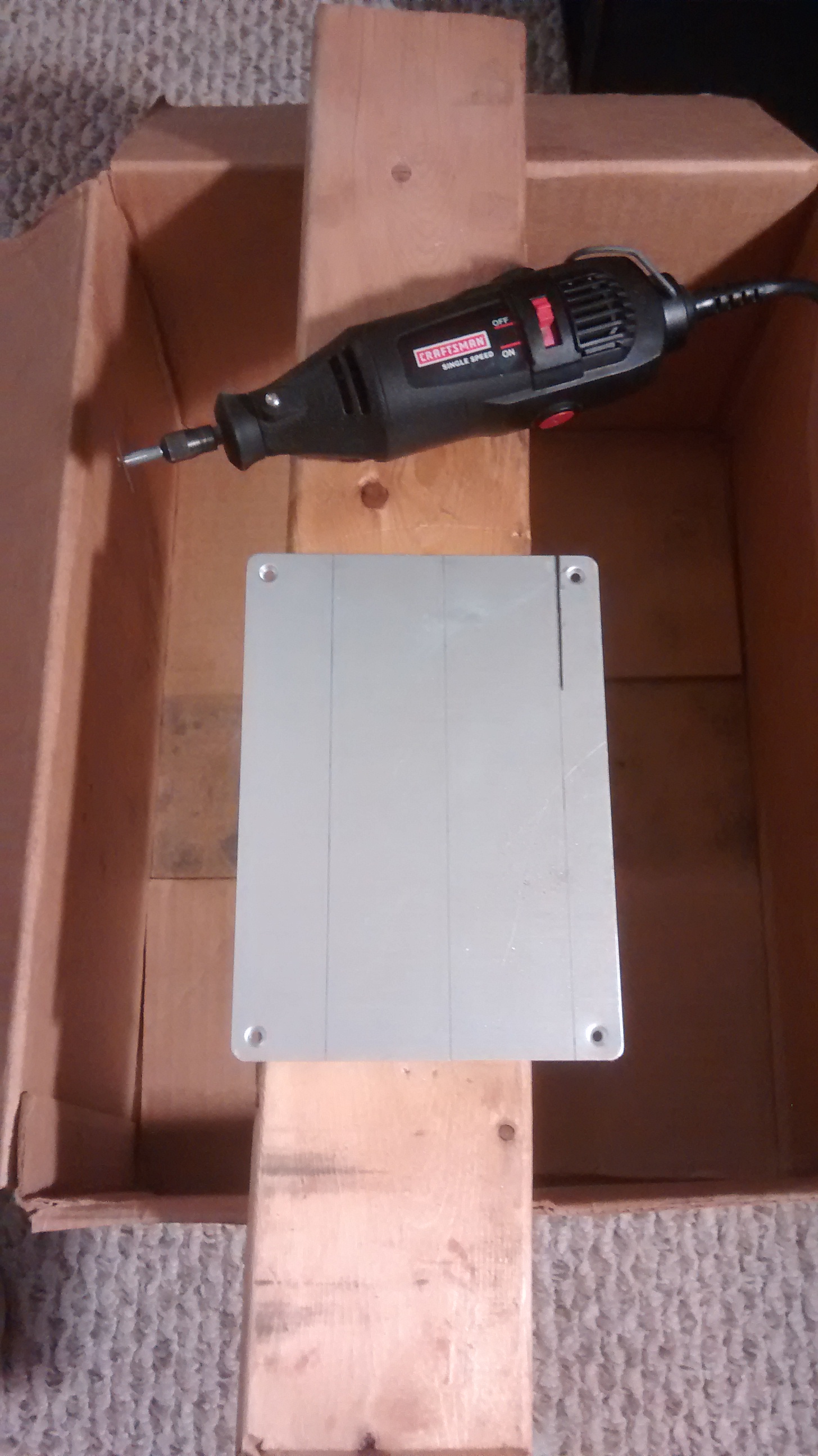
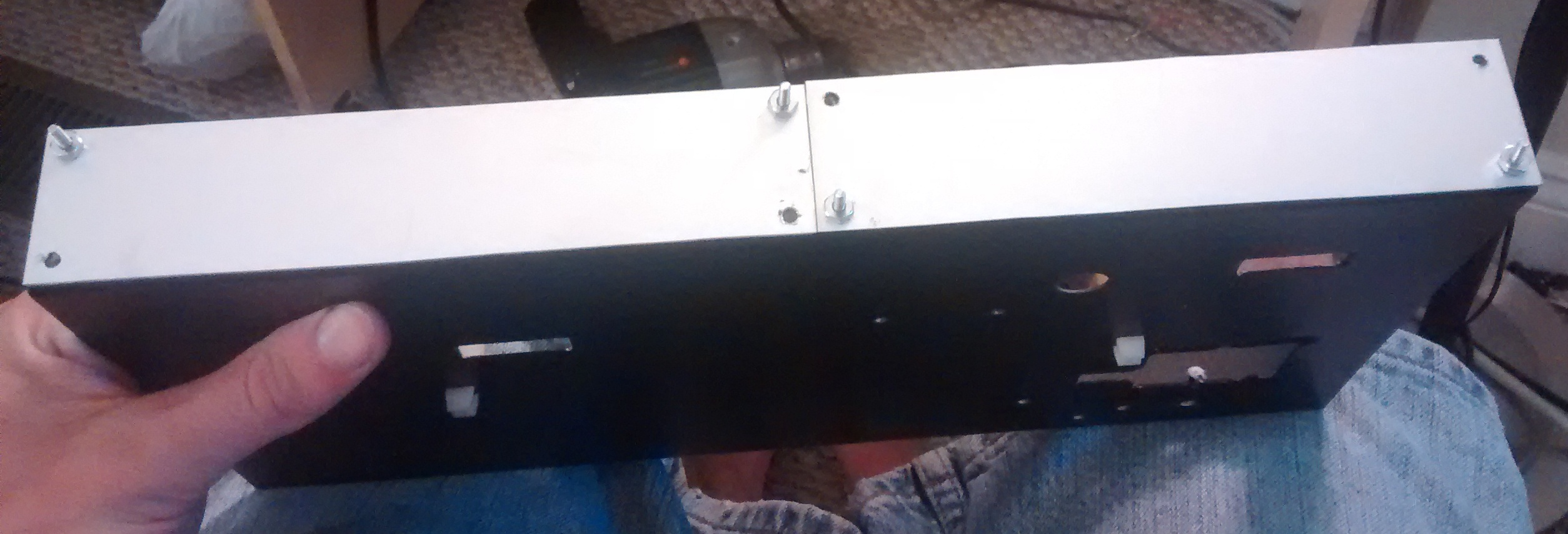
Next I started cutting metal. I did not want to use the existing face plate from the Peavey Blazer. There were too many holes for knobs that wouldn’t exist, so recycling this would just be ugly. Instead, I had some silvery brushed steel panels laying around that I decided to cut up and make a new face plate from. I cut two strips that would cover the front panel, and meet at a seam in the middle. One of the two I cut about 1cm shorter to arrive at the chassis length, but this is unnoticeable.
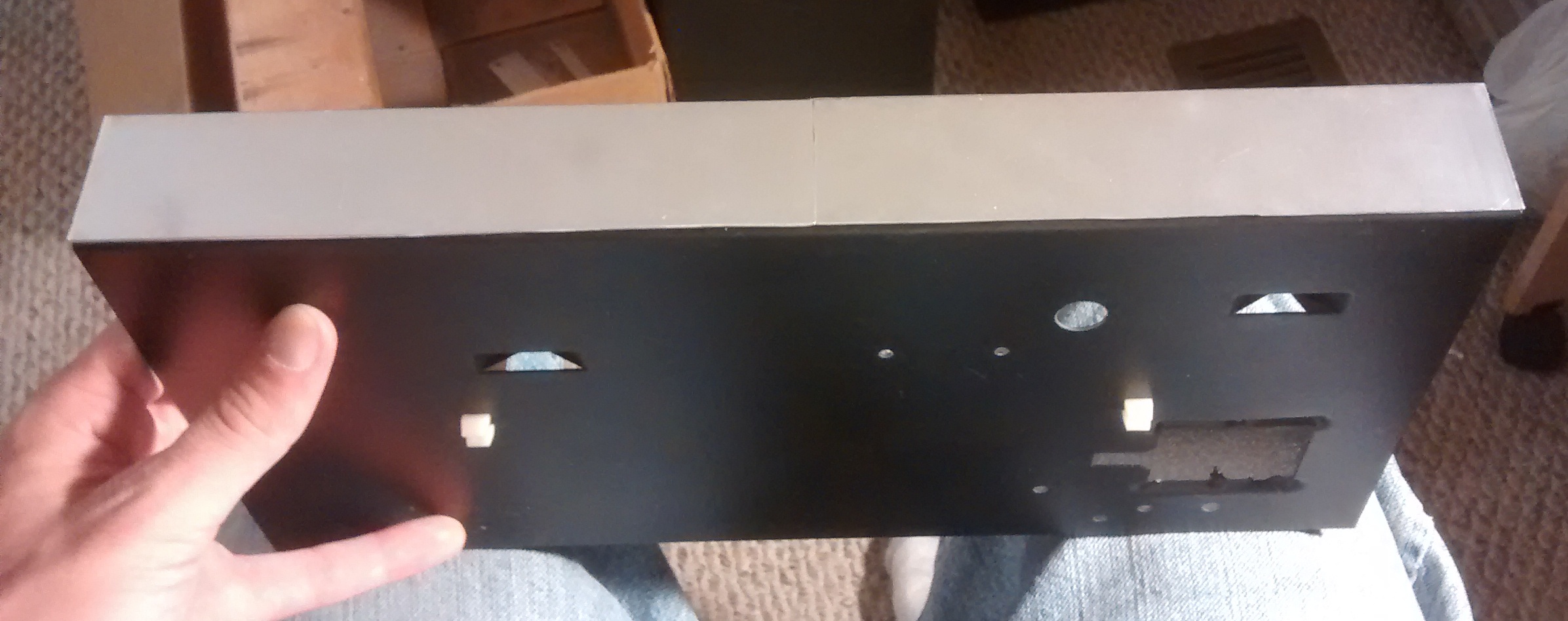
Next I cut rectangles into the Blazer front panel where my new controls would be, making sure to leave about 1.5cm of the original panel remaining where the ends of the new face plate segments would be. The rectangles cut in the old panel allow me to mount my controls directly to the brushed steel face plates, and the leftover metal behind the end of each face plate segment would provide a surface to mount them.
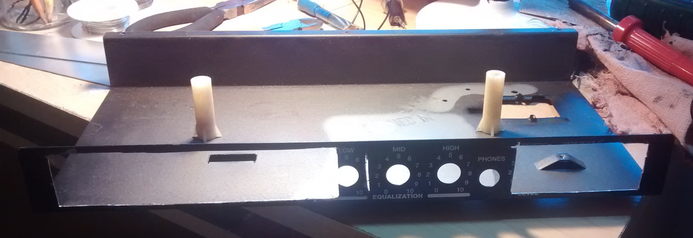
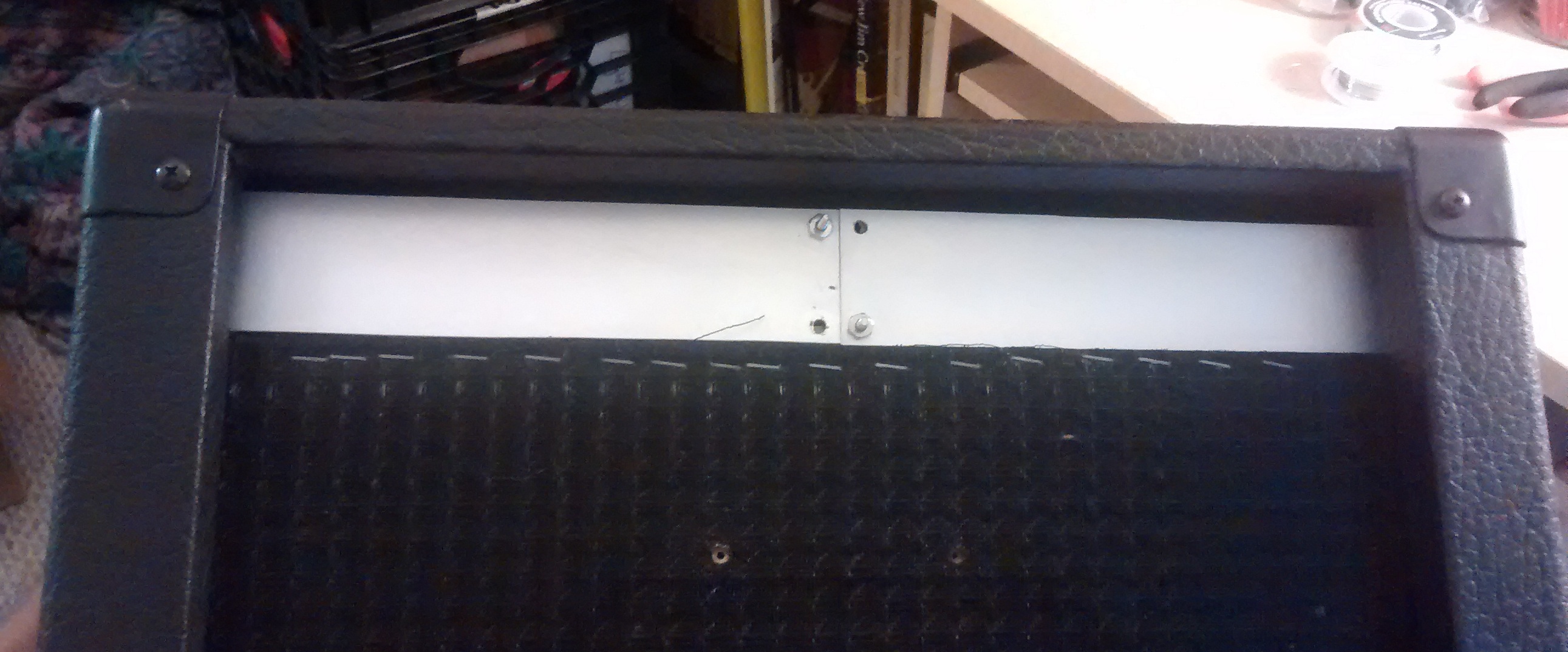
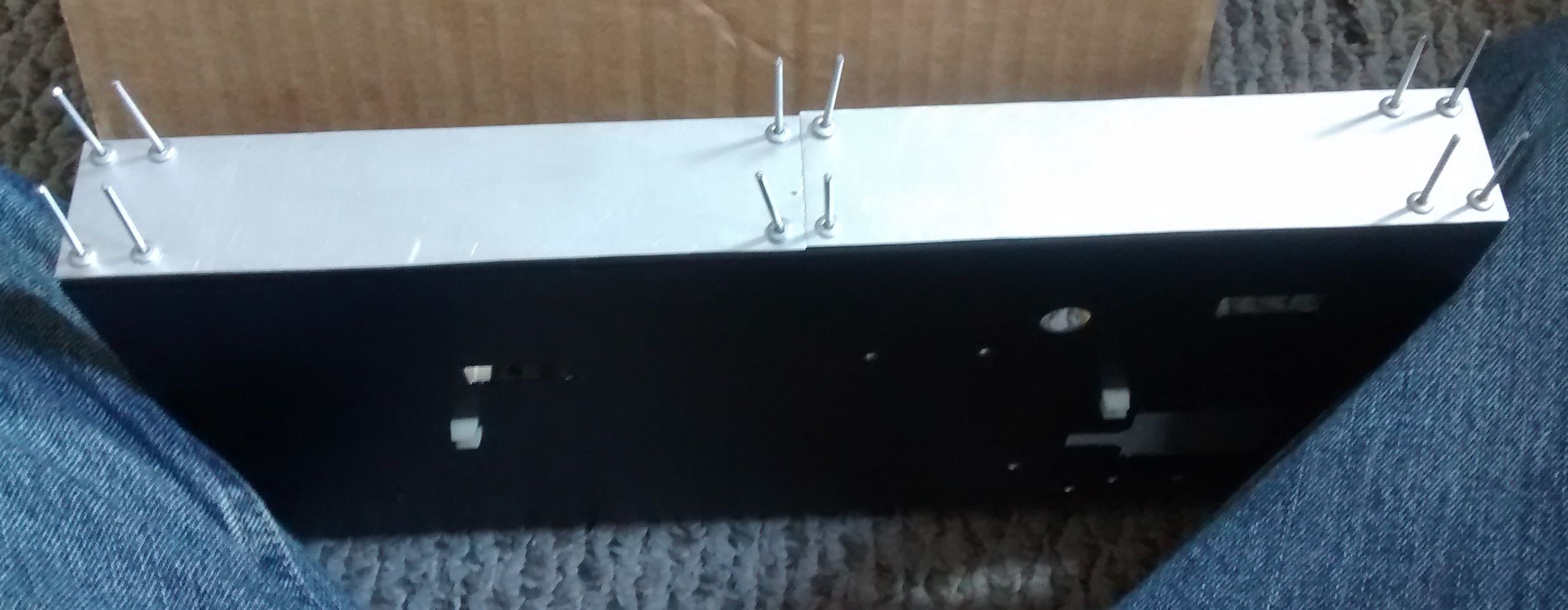
I decided rivets would look pretty cool (read: vintage), and marked the corners of each brushed steel segment. I had eighth-inch rivets on hand, so I drilled holes that were nine sixty-fourths of an inch in diameter to make sure they would fit. This took a long time and a bit of trial and error. I drilled the brushed steel face plates before attacking the old panel. If I had a drill press, maybe I could have done them both in one go? In any case, drilling the new face plates was easy, aligning them to the old panel was not so much (at first). I tapped and drilled my first two holes in the steel face plates, and quickly realized they did not line up to the Blazer panel holes. The way I worked around this was to put a nut and bolt through the new face plate and rear panel, then drill the remaining holes using the new face plate as a guide adding additional nuts and bolts as I went for more stability. This worked well, and for the Blazer panel holes that were off just enough to keep rivets from fitting I simply drilled again slightly larger.
Upon test fitting I realized the outer holes were not visible, which looked… not as good as I intended.
To remedy this, I decided to drill four more holes for rivets that would be visible. These rivets wouldn’t actually be fastening the face plates to anything, they would be purely aesthetic to complete the look I wanted.
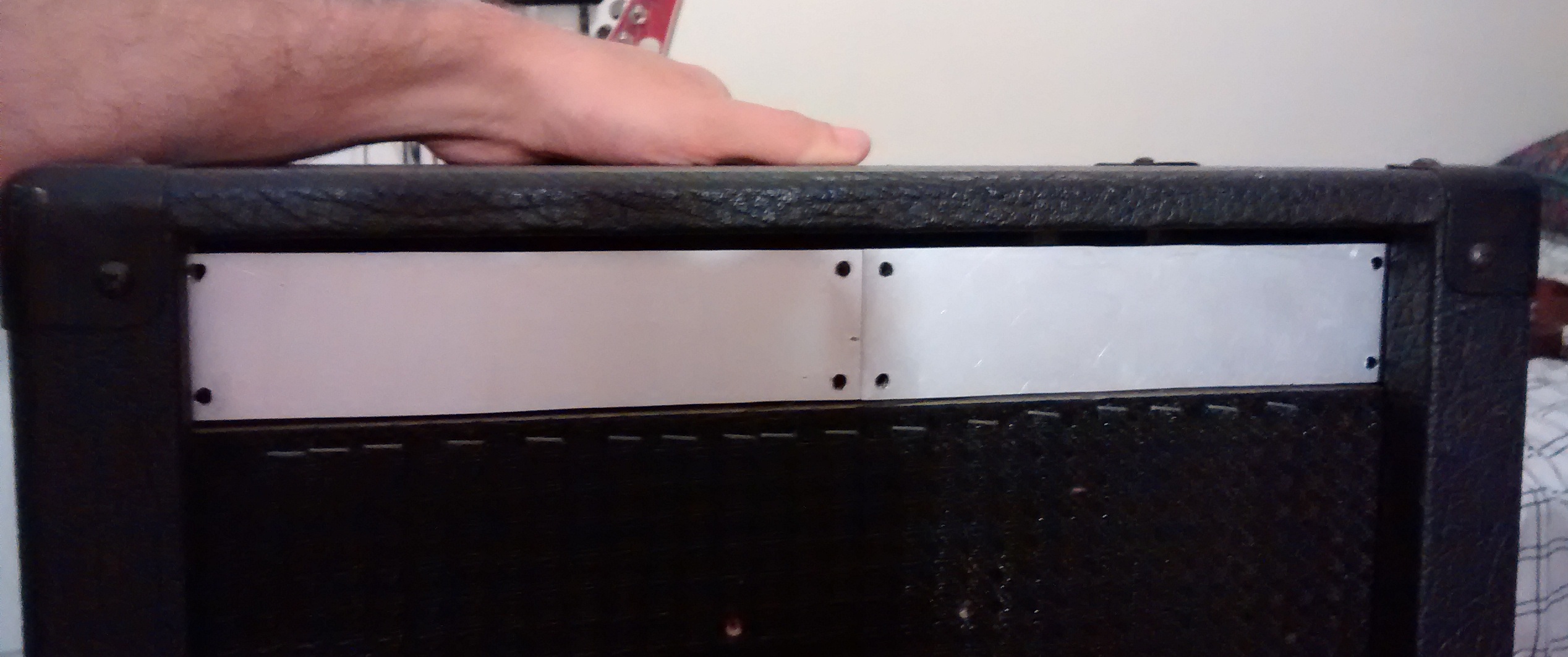
At this point, I’ve reached as much as I feel comfortable doing until the transformers arrive and I can take some more measurements. Next up will be mounting the transformers and terminal strips to the chassis, and cutting holes for the tube sockets. Afterwards I can start soldering up a circuit and tweaking things. The front panel control holes will probably come last, once I finalize the circuit design and know how many holes I will actually need. Stay tuned!

