Build a blinking safety light for your bicycle
I needed a blinking light device to attach to my bike in the spirit of “Dear cars, please don’t hit me”. I could’ve just purchased one for less than the cost of building one, but that’s not as much fun. Fun is really the main reason I do these things. So I built my own, and I’m going to provide you with the information necessary to do the same. Here are the parts you will need:
Radio-shack esque perfboard to solder your components on
1x 555 timer IC 3-5 LED’s of whatever color you like (the must all be the same though!)
1x 100 ohm resistor
1x 100K ohm variable resistor/potentiometer
2x 1K ohm resistor 1x 9v battery clip with lead wires
1x 9v battery
1x 2-pole on/off switch Small plastic/metal/other enclosure
You will of course need a soldering iron and solder, as well as a drill with a 3/8th inch drill bit for the holes in your enclosure that the LED’s will go in. A Dremel tool with cutting wheels may be optional if you feel like you can cut the perfboard with scissors or some other tool. The circuit I used is a very common one. You can do a google search for “555 timer LED blinker” and find hundreds of schematis that will fit the bill. Here is the schematic for my particular flavor of LED blinker:

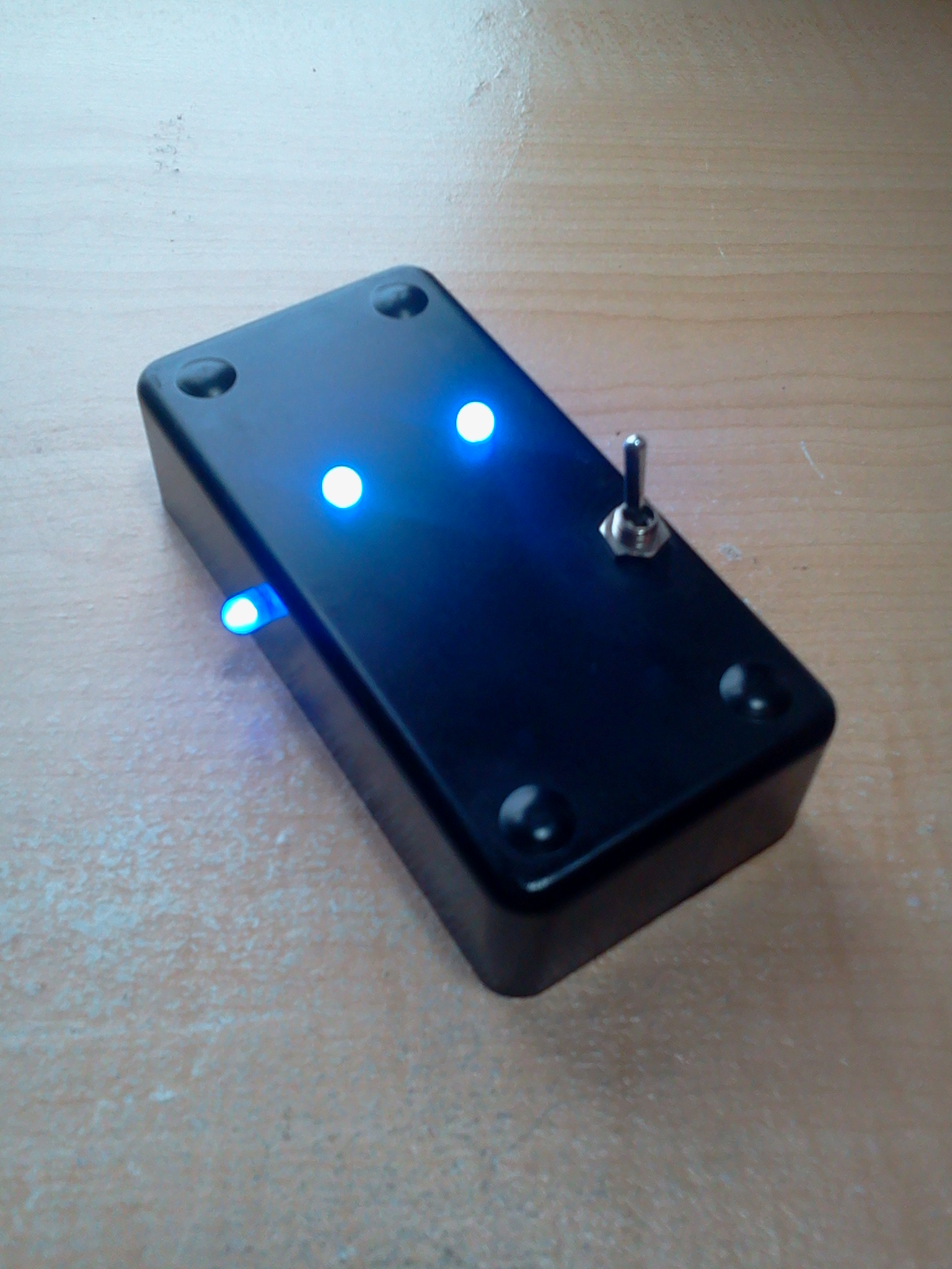
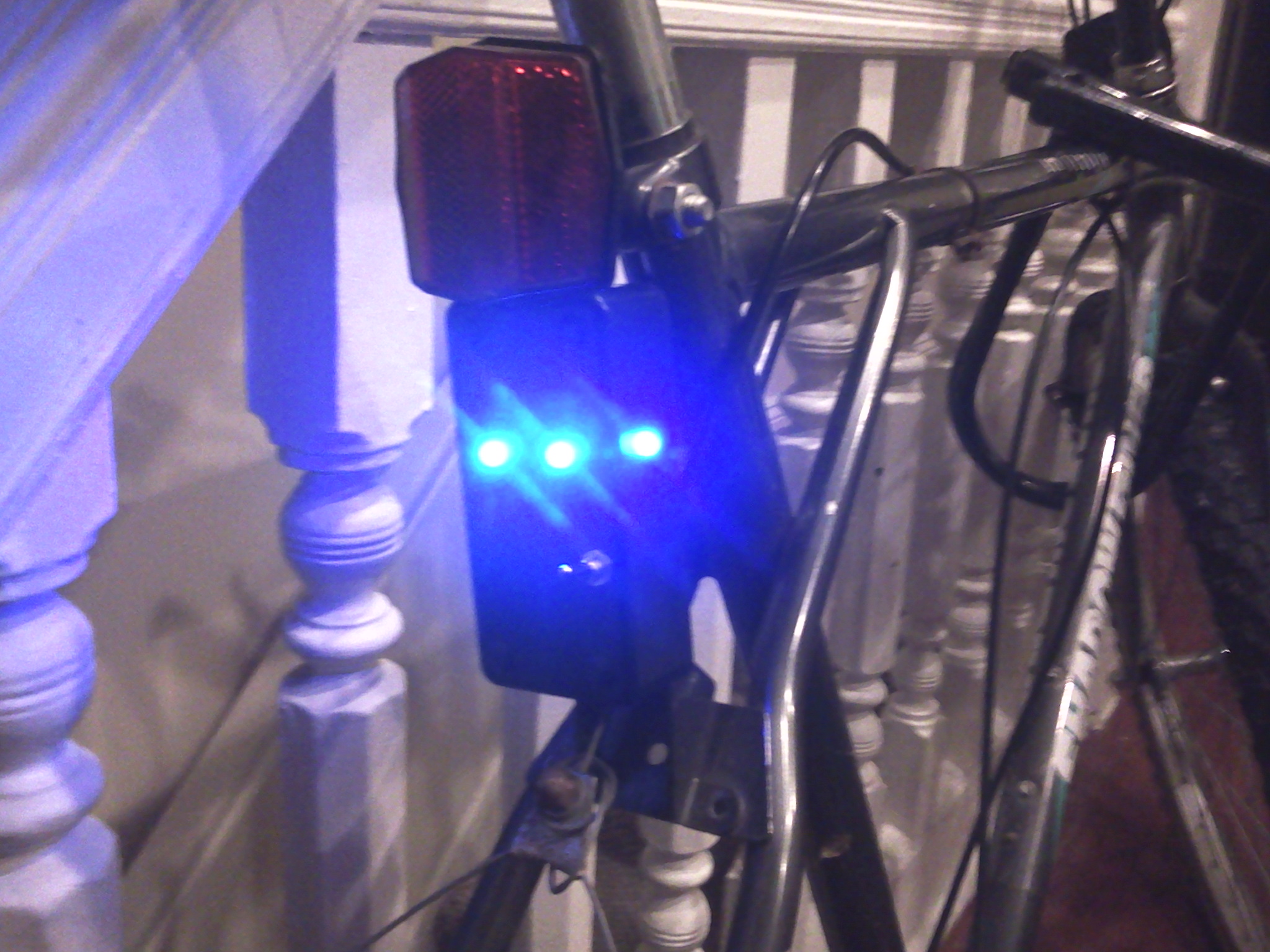
The variable resistor (100K) in the schematic above may not be included in other designs with a fixed blink rate, I included it here so that the blink rate can be user adjustable from about 1hz to several hundred hertz. I didn’t include mounting hardware in the parts list because you will need to do some thought on your own to decide how your enclosure will attach to your particular bicycle. My bike has a small metal piece above the rear tire with holes in it, so it was only logical to attach my enclosure here with a nut and bolt. Wire this circuit up on your perfboard and insert it into your enclosure. Mount it on your bike and you’ll hopefully have something like this!
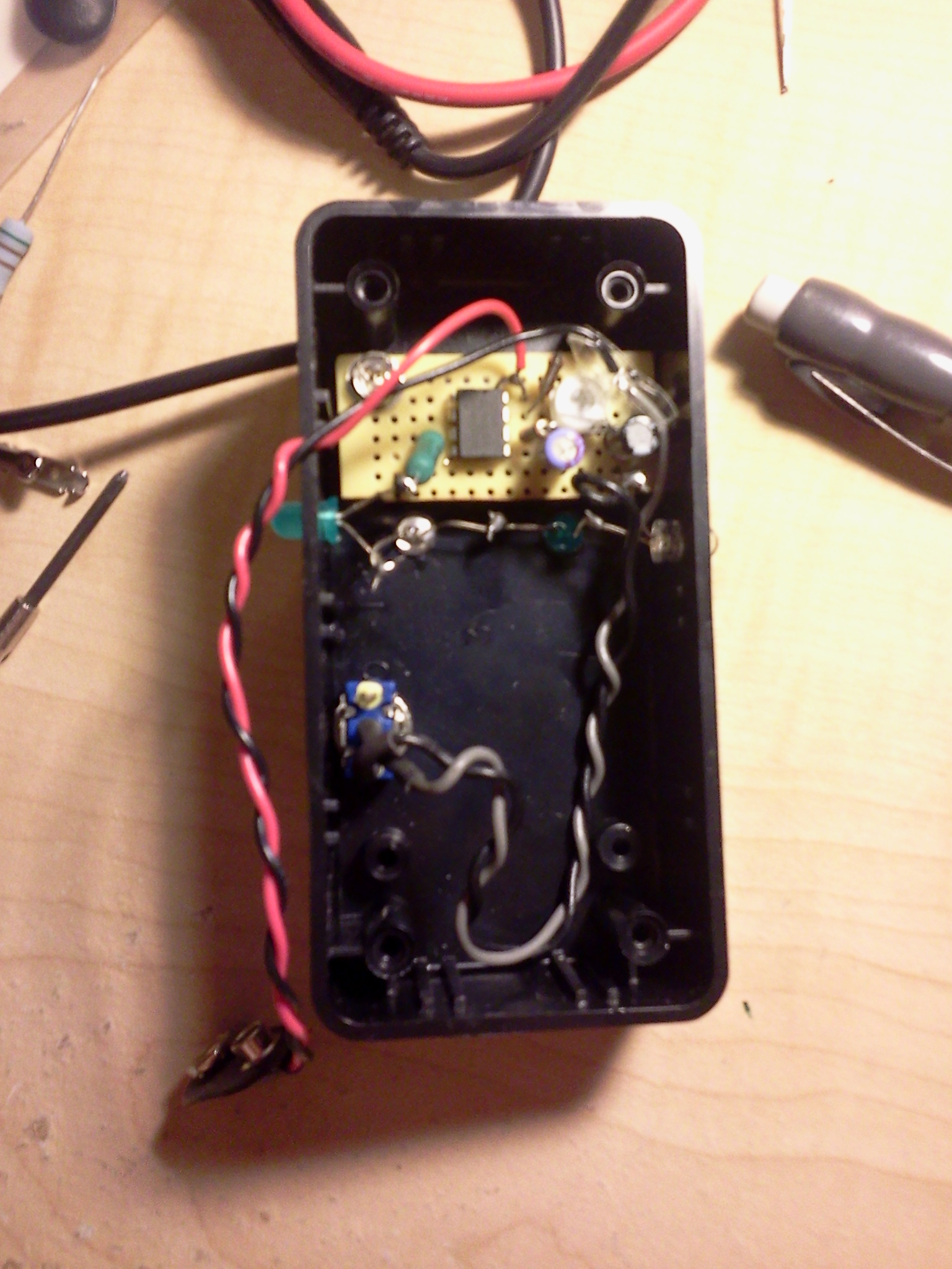
Make sure you wire your LED’s in parallel! I had been testing the circuit on my breadboard with a 9v DC wall adapter as the power supply, this is slightly different from using a battery, as it will deliver ~14v to a lightly-loaded circuit. I had wired my LED’s in series, and with the wall adapter everything worked fine. However, when powered by a 9 volt, the four LED’s I had wired in series dropped more voltage than the 9 volt could deliver, so the circuit failed to operate. The easy fix for this is of course to wire the LED’s in parallel, so that collectively they can only drop the same voltage as a single LED would (which is ~1.5 volts).
Note the LED’s wired in series in this photo, this is NOT what you want!
This photo has identical LED’s wired in parallel, which will work much better.
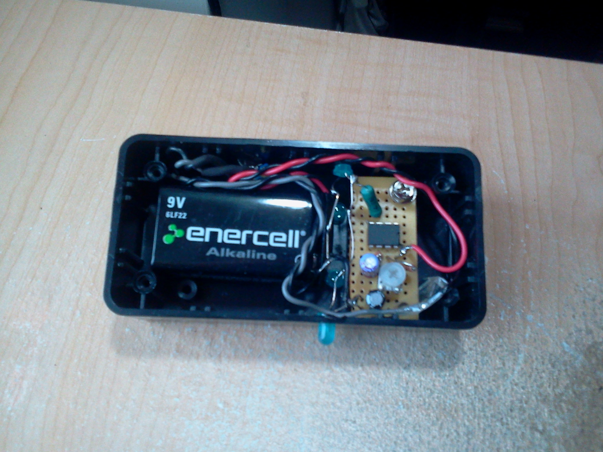
You can see how everything is laid out in the enclosure in the photo above. I soldered the circuit to the perfboard before cutting the excess off with a Dremel. The screw holes on the board don’t line up with the holes in the enclosure perfectly, so I only used one corner screw to hold it in place. It’s a pretty tight fit for everything, but at least no space was wasted. I don’t have a photo of the back panel, but there is a quarter-inch hole for the bolt that is used to attach it to my bicycle. Your bike might not have the same mounting mechanism, so as I mentioned above you will have to figure out how to mount it yourself. There is also a smaller hole directly above the screw head on the trimpot, this is so that you can adjust the blink rate with a screwdriver without ever taking the device off your bike. The finished project looks like this!